This article is a summary of the paper “Open-Source Framework for Co-Emulation using PYNQ” which was presented at the DVCon U.S. 2021 Conference.
Table of Contents
- Resources
- What is co-emulation?
- What is OFC?
- Basic Concepts
- User Integration
- Conclusions
- DVCon U.S. 2021 Experience
Resources
The OFC code is provided as an open-source library under Apache License 2.0.
You can download the OFC from GitHub.
The DVConUS 2021 recorded presentation, the slides and the paper are available in our AMIQ Resources section.
What is co-emulation?
Accelerating verification through co-emulation consists of translating not only the DUT, but also part of the drivers and monitors of the testbench from software into an FPGA board. By doing so, receiving and processing stimulus by the DUT will be optimized regarding time-consumption due to the parallelism of the hardware system.
By translating the DUT from the simulated testbench into the FPGA board, all interactions with it must be redefined, as the testbench no longer has a direct connection to the DUT. Therefore, to accelerate the verification through co-emulation it is necessary to create and place synthesizable drivers and monitors into the FPGA to handle direct connection to the DUT. These modules are further called HDL components. On the other hand, the testbench still requires drivers and monitors to handle transactions between the verification environment and the hardware platform. These are further called HVL components.
What is OFC?
Due to the lack of accessible solutions regarding co-emulation verification we chose to develop a modular, open-source framework meant to provide an accessible way to achieve hardware integration within a testbench: the Open-source Framework for Co-emulation (OFC).
Usually, the hardware platform used for co-emulation contains an FPGA and a processor acting as an FPGA controller. This architecture requires two connections:
One between the host machine, containing the testbench, and the FPGA controller
One between the FPGA controller and the FPGA logic
The OFC provides one component for each of the required connections.
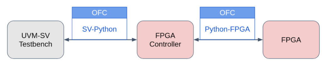
Figure 1. OFC Overview
For achieving a co-emulation environment the OFC SV-Python connector and the OFC Python-FPGA connector should be used together. Although, you can also use them separately:
- The OFC SV-Python module can connect your UVM-SV testbench to a Python environment
- The OFC Python-FPGA module can connect your HDL design to a Python environment
Basic Concepts
The OFC framework provides most of the components necessary in order to achieve a co-emulation environment.
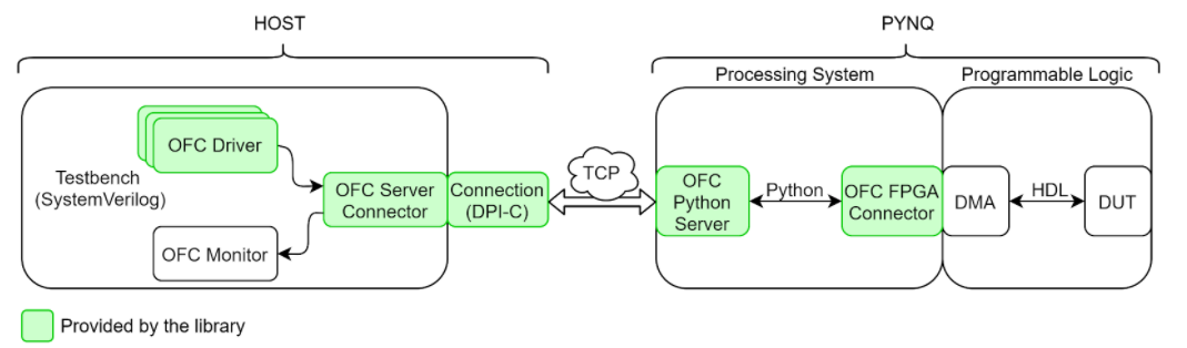
Figure 2. OFC Architecture
The OFC framework was tested on the hardware platform Pynq, where the FPGA Controller is called the Processing System (PS) side and the FPGA is called the Programmable Logic (PL) side.
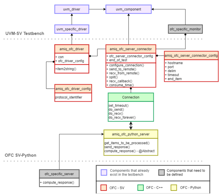
Figure 3. Class Diagram of the OFC Framework
Layer 1: Host – Verification Environment
The SystemVerilog testbench for co-emulation should do what a simulation testbench does without connecting directly to the DUT. The OFC framework provides an HVL driver (OFC Driver) which sends stimuli to the DUT through a proxy component that manages the connection with the hardware platform. This component is called OFC Server Connector and it plays the role of the client in the TCP connection with the PS side of the Pynq board. For more information about the socket communication used check out the Non-Blocking Socket Communication in SystemVerilog Using DPI-C article.
All components from the testbench should be independent of clock cycles and timing constraints, as the clock is generated in the FPGA, not simulated in the testbench. Only the drivers and monitors have to change, assuming that the rest of the testbench does not depend on time constraints.
Layer 2: PYNQ – Processing System
On the PS side of the Pynq board the framework provides the OFC Python Server that manages the requests from the testbench. The server can make use of the OFC FPGA Connector in order to send stimuli to the DUT in case the goal is to achieve a co-emulation environment, or it can process locally the requests received if the goal is to connect the testbench to the Python environment.
The OFC FPGA Connector is using the Pynq API provided by Xilinx to program the PL side of the Pynq board and to transfer data to and from the DUT. In order to transfer data, DMA modules are used.
Layer 3: PYNQ – Programmable Logic
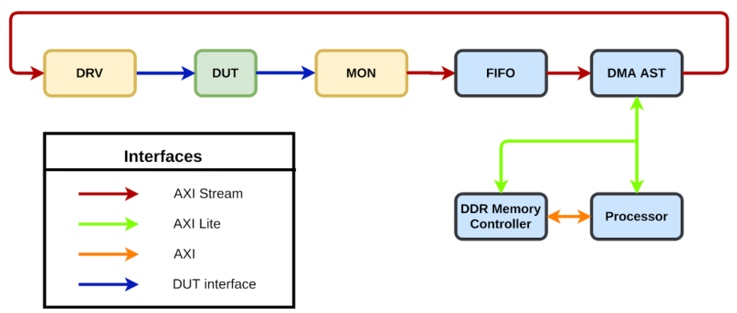
Figure 4. PL side overview
The hardware side is responsible for transferring items received from the software to the DUT and transferring the results back to the software for processing. To accomplish this connection, the DMA IP is used. This IP is provided by Xilinx and can be integrated through the Vivado Design Suite. Based on your preferences, you may choose a different FPGA board and/or a different software tool for programming the FPGA logic.
The DMA communicates with the emulated design through the HDL components. The HDL components implement two interfaces: one for communicating with the DMA and one for communicating with the DUT. The DMAs interfaces used to communicate with the programmable logic side are based on the widely adopted AXI4-stream protocol. Therefore the HDL components contain an AXI4-stream slave interface for receiving from the DMA (drivers) or an AXI4-stream master interface for transferring to the DMA (monitors).
User Integration
There are four steps in order to integrate the OFC framework within an existing testbench.
Step 1: Replacing the original drivers with the OFC Driver
You can replace the usual UVM drivers with the OFC driver using the UVM factory override.
The only thing that is necessary for the OFC Driver to work as a “plug and play” component is making sure that the items have a pack function, as the driver uses this function to convert items into messages. Items may have their fields registered with UVM or a custom pack function can be defined.
Step 2: Creating a specific OFC Monitor
Creating your own OFC Monitor is necessary as all items are received within the OFC Server Connector and there is no way for the framework to know where to send those items. The OFC framework has no knowledge about your verification environment architecture.
The OFC Monitor receives string items from the OFC Server Connector which should be converted into UVM items and sent through the appropriate analysis ports.
Step 3: Computing response within the Python Server
The messages from the testbench, through the OFC Server Connector will be received by the OFC Python Server. The server will split the messages into a list of “string” items and will pass them to a function called “compute_response()” that you need to define. This function has been left to the user’s responsibility in order to offer flexibility regarding the timing for sending stimuli to the DUT or even the possibility to not send stimuli to the DUT at all (in case the goal is not a co-emulation environment).
For a co-emulation environment, this function should:
- Convert the “string” items into items that will be used by the HDL drivers
- Send the converted items to the DUT through the OFC Python-FPGA component
- Receive results from the DUT through the OFC Python-FPGA component
- Return the processed items as a list of strings
For other purposes, when co-emulation is not the goal, only the fourth point should be considered.
Step 4: Creating HDL Components
The fourth and the final step is implementing the HDL Components within the Programmable Logic side. These components are drivers and monitors that can be timed as opposed to the rest of the testbench. The HDL Components should be linked to the proper DMA module, so that they can be accessed from the OFC FPGA connector.
Debugging the programmable logic side of the hardware platform can be quite difficult without any waveforms to be analyzed. One way to debug the FPGA design is to use the ILA IP core available in the Vivado Design Suite. For more information on how to create and configure the ILA core you can check out this article from RealDigital.
Conclusions
A co-emulation environment implies splitting drivers and monitors into timed and untimed components and connecting them. The connection proposed through the OFC framework is based on a client-server communication and the usage of the DMA.
The speed-up is dependent on several factors, among which:
- The amount of logic that is translated into the hardware platform
- This is the reason why co-emulation has a greater speed-up than co-simulation (which requires translating only the DUT into the FPGA logic).
- Better performance will be achieved for complex designs, therefore you should consider using a co-emulation solution when verifying complex designs.
- The number of DMA accesses
- The number of DMA accesses should be limited to the minimum necessary if you want to achieve better performance.
- To reduce the number of DMA accesses you can send multiple stimuli within the same DMA access, but keep in mind that FPGA resources are also affected.
- Context switches
- Having fewer context switches between send and receive operations can also lead to an increase of performance.
- You can manage the context switches from within the OFC Python Server or from within the OFC Server Connector
The OFC is a modular framework with two components that can be used together or separately:
The first component is the OFC SV-Python which can be used for communication between a SystemVerilog testbench and a Python environment. The second component is the OFC Python-FPGA which can be used for communication between Python and the Programmable Logic side of the Pynq board. The two components can also be used together for achieving a co-emulation environment.
The framework requires little integration effort, can be easily updated, and is open-source and tool agnostic.
DVCon U.S. 2021 Experience
The OFC was presented on 3rd of March during the Potpourri Session lead by Josh Rensch from Semifore. The paper was awarded with the 3rd place for the “Best Paper”.
During the Q&A session the following questions were answered:
Does the TCP connection between the UVM-SV testbench and the Python Server support TLS or any other way to ensure network security? Would you recommend that this framework only be used behind a firewall?
In our setup we used a private network. The library itself does not provide this kind of security, so you have to handle that at a different layer. The library provides only the connection itself and the mechanism for sending and receiving data.
If we would like to use 2 OFC ports with different HDL implementations: if each testbench port operate with different non-multiple frequency, how do we solve synchronization between those ports?
So far we only managed to set it up with a single connection using OFC. This could be a next step for us. The time we had to develop this framework only allowed us to set it up for one connection. With further development, the OFC could allow the user to connect multiple times. As a side note, maybe it could also be used if you instantiate your RTL multiple times and run environments in parallel.
What about debugging and/or waveform generation support? How are DUT probes done?
It’s definitely harder to debug a co-emulation environment compared to a simulation one. The OFC provides debug messages which include sent and monitored items, but it doesn’t offer support for visualizing the actual waveforms. In order to debug using waveforms you can use custom IPs that you can attach to your design. Those IPs have an internal memory that can record the bus level wiggling of the pins. In our development we used an ILA core within the Vivado tool to visualize the waveforms. This method is limited by the FPGA and the tools you are using.
What is the maximum frequency (transaction per second) could be achieved with OFC solution in case of sequentially repeating send then get data back?
If we define frequency as the time from generating one sequence item in the testbench going through the RTL in the co-emulation environment and than sent back to the testbench, we haven’t looked into that too much because it implies too much overhead. The more that you buffer the items before sending them to the other environment (SV-Python-FPGA), the more speed up you get. If you run transactions one by one then you will actually be slower than the simulation. So that’s not a real use case.
So if you hit a bug or issue, would a reproducible replay in a full simulation be an option?
It depends on the type of testing that you have. The more random the test cases are in normal simulation, the less likely you are to reproduce the problem. That’s because when you use a co-emulation environment you have to take into account some trade offs regarding the precision of controlling the bus level. When you implement the HDL drivers which actually communicate with the DUT you don’t have the same control you have with UVM drivers.
2 Responses
This is great.
I am an engineer working in a Japanese AMIQ EDA distributor.
1) Which Pynq is used? Original Pynq board with 7020? or a recent one with UltraScale+ MPSoC? The current device has more capacity and faster circuits.
2) If the Ethernet link is replaced with PCIe, what gain can we expect?
3) What is the productization plan?
Many people supposed this kind of system is possible, but much work is needed to prepare a stable and well-documented ready-to-go system, which is essential to the rest-of-us.
Hi Junichi,
We’re glad you find it interesting!
1) The PYNQ board used is the one with XC7Z020.
2) We can most likely expect an increase in performance, as the TCP connection is one of the main bottlenecks of this architecture. In a conversation with a DVCon participant, he mentioned that, using a similar architecture and replacing TCP connection with PCIe, he obtained results revolving around 0,6-1M transactions per second, where a transaction size was 1/2/4/8/64 kB.
3) There is currently no productization plan in place.
Best regards,
Ioana