This post explains the functional verification of counters and it is part of a series of posts exploring functional coverage patterns. The first post in the series was Functional Coverage Patterns: Bitwise Coverage.
Table of contents
- What is a Counter?
- Counter Verification
- Regarding Synchronicity
- Reset Value Coverage
- Clear Value Coverage
- Overflow and Underflow Policy Coverage
- N-bit Up/Down Counter Value Coverage
- Gray Code Counter(GCC) Value Coverage
- Modulo-N Counter Value Coverage
- BCD Counter Value Coverage
- LFSR Counter Value Coverage
- Bit Stream Counter Value Coverage
- Notes
- Further Study
What is a Counter?
A counter is a digital component that updates its value by a fixed or programmable amount at given moments in time (e.g. every clock cycle, every time a signal is asserted, etc.).
We can categorize counters in terms of the following dimensions:
- Synchronicity: asynchronous, synchronous
- Initial/Reset Value: constant value, programmable
- Increment Value: fixed, programmable
- Output Value: N-bit, bit stream, pulse
- Counting Sequence: up/down (or natural binary code), Gray code, modulo-N, BCD counters, pseudo-random
- Overflow Policy: wraparound, saturate
- Implementation: binary up/down using flip-flops, ring counters, Johnson or twisted ring counter, linear-feedback shift registers, cascaded counters
- Usage: arithmetic counting, encoded counting, pseudo-random generator, frequency prescaler, statistics counters, bit-stream (de)scrambler, test pattern generator
Counter Verification
In functional verification data/temporal checks and coverage definitions are crucial to the quality of the verification and counters are no exception to this.
I consider the following checks to be mandatory:
- Counter value is updated correctly (e.g. incremented, decremented, correct Gray code, correct LFSR value or bit stream etc)
- On the first cycle after reset the counter value has the correct reset value (i.e. a predefined reset value or an input reset value port)
- On clear, the counter value is set to the correct clear value (i.e. a predefined clear value or the input clear value port)
- Upon load, the counter value is set to the load value (i.e. the input load value port)
- Where the system frequency can vary, the counter works correctly for a given set of clock frequencies. (This is an implicit check that is passed if all other checks pass for a given set of clock frequencies.)
Coverage definitions are explained in more detail in the following sections.
Regarding Synchronicity
A counter is synchronous if all its flip-flops are connected to the system clock. The synchronicity aspect does not impact the proposed checks and coverage definitions.
If the system clock can vary within a given frequency range, but remains constant during simulation, then you should cover the minimum, maximum and middle values of the frequency range, regardless of the synchronous nature of the counter.
Sampling time: immediately after you perform a counter value check.
Reset Value Coverage
The most common behavior for a reset scenario is depicted in the waveform below:

If the reset value is a pre-defined constant, then it is sufficient to check that the reset value is applied correctly and use the reset value check coverage instead (see Notes).
However, there are some cases (e.g. bootstrap values of a SERDES), where the reset value of a counter or register is configured during reset:

In this case you should cover a set of reset values using power-of-two coverage (see also here):
covergroup reset_value_cg with function sample(bit[WIDTH-1:0] x, int position);
   reset_value: coverpoint position iff (x[position]==1 && ((x&(~((1<<(position+1))-1)))==0)) {
      bins b[] = {[0:WIDTH-1]};
   }
endgroup

function void sample_reset_value(bit[WIDTH-1:0] x);
   for(int i=0;i<WIDTH;i++) begin
      reset_value_cg.sample(x, i);
   end
endfunction
In order to enssure that reset_value is sampled correctly, it should be set to X at all times except for the cycle during which the reset_value_set is asserted.
Sampling time: first cycle after reset.
Clear Value Coverage
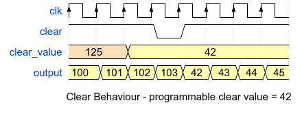
Counters that support a 'clear' or 'load' feature will set the counter to a value that is either a constant or an input. The most common behavior for a clear scenario is depicted in the waveform below:

As with resets, the clear value can be programmable:

The functional coverage definition is similar to the reset coverage definition:
covergroup clear_value_cg with function sample(bit[WIDTH-1:0] x, int position);
   clear_value: coverpoint position iff (x[position]==1 && ((x&(~((1<<(position+1))-1)))==0)) {
      bins b[] = {[0:WIDTH-1]};
   }
endgroup

function void sample_clear_value(bit[WIDTH-1:0] x);
   for(int i=0;i<WIDTH;i++) begin
      clear_value_cg.sample(x, i);
   end
endfunction
Sampling time: first cycle after clear signal is asserted.
Overflow and Underflow Policy Coverage
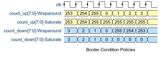
Arithmetic counters must be able to handle border conditions like overflow or underflow. They do this by implementing one of two policies:
- wraparound: once the maximum value is reached, the next update will set the counter to the minimum value
- saturate: once the maximum value is reached the counter will not update the value until the next clear or reset
The picture below shows the border condition policies for UP and Down counters:

Border conditions handling, requires the counter to take a decision on the next value to transition to. You need to define a transition item based on the value of the counter and limited to values in the vicinity of the border, as demonstrated below:
covergroup cg with function sample(int unsigned value);
   cnt_value_wraparound : coverpoint value {
      bins zero2one    = (0=>1);
      bins one2two     = (1=>2);
      bins maxminone2max = (32'hFFFF_FFFE=>32'hFFFF_FFFF);
      bins wraparound  = (32'hFFFF_FFFF=>32'h0000_0000);
      bins others      = default sequence;
   }
   cnt_value_saturate : coverpoint value {
      bins zero2one    = (0=>1);
      bins one2two     = (1=>2);
      bins maxminus1tomax = (32'hFFFF_FFFE=>32'hFFFF_FFFF);
      bins saturate  = (32'hFFFF_FFFF=>32'hFFFF_FFFF);
      bins max2zero  = (32'hFFFF_FFFF=>32'h0);
      bins others      = default sequence;
   }
endgroup
With the saturate policy, the wraparound transition can still occur if a reset or clear is actioned (either hardware reset or write/read-with-clear type operations).
Sampling time: every time the counter changes its value. With the saturate policy you can also sample the values right after reset/clear so as to cover the case of wraparound from maximum value to minimum value.
In order to achieve border conditions you need to bring the counter close to a border value and then let it transition naturally. Depending on the size of the register, you can allow the counter get to reach a border value naturally OR, in the case of large counters (e.g. 32-bit), you can force the counter into a near-border value and then allow it to transition naturally.
N-bit Up/Down Counter Value Coverage
What you cover depends a lot on the size of the register: while you can probably cover all values of a 16-bit register, this will not be practical for a 32-bit one. The former case is trivial, while in the latter case you will have to reduce the value space to a “min, max and in-between” type of range. For a 32-bit register you can reduce it to something like:
covergroup count_cg;
   count_value: coverpoint {
      bins min = {0};
      bins one = {1};
      bins middle = {[2:32'hFFFFFFFD]};
      bins maxminus1 = {32'hFFFFFFFE};
      bins max = {32'hFFFFFFFF};
   }
   // You can also include a transition for wraparound or saturate policies.
endgroup
Sampling time: every time the counter value changes.
Gray Code Counter(GCC) Value Coverage
Gray Code counters update their values based on a Gray code scheme in which only 1-bit toggles the current value to the next. A GCC cycles through the list of code words, and will therefore always wraparound.
The table below contains an example of Gray codes for N=4:

As the GCC cycles through the list of codes, you will need to cover all values and legal transitions. But is this practical? The implementation of the coverage might be tedious even for small N values, given that you have to specify all legal transitions and filter out the illegal ones "manually". However, by studying the details of the implementation you might be able to simplify this process. For example, I take the most common GCC implementation based on a binary UP counter:
always @ (posedge clk) begin
   if (rst) begin
      binary_count <= 0;
      gray_count   <= 0;
   end else begin
      binary_count <=  binary_count + 1;
      gray_count   <= {binary_count[3:3], binary_count[3:1] ^ binary_count[2:0]};
   end
end
In this case you can model the GCC in your environment and do the following:
- check that the GCC values are correct
- cover UP counter values using power-of-two coverage
You should also check/cover that every bit toggles from 0-to-1 and 1-to-0 to enssure connectivity (see also here):
class bit_toggle_cg_wrapper; // covergroup wrapper class
   covergroup bit_toggle_cg(input int bit_idx) with function sample(bit x, int aidx);
      bit_transition: coverpoint x iff (bit_idx == aidx) {
         bins zeroone = (0 => 1);
         bins onezero = (1 => 0);
      }
   endgroup

   function new(string name="bit_toggle_cg_wrapper", int aidx=0);
      bit_toggle_cg = new(aidx);
      bit_toggle_cg.set_inst_name(name);
   endfunction

   function void sample(bit x, int aidx);
      bit_toggle_cg.sample(x, aidx);
   endfunction
endclass
bit_toggle_cg_wrapper bit_toggle_cg_w[WIDTH];
function void sample_bit_toggle(bit[WIDTH-1:0] x);
   for(int i=0;i<WIDTH;i++)
      bit_toggle_cg_w[i].sample(x, i);
endfunction
Sampling time: every time the counter value changes.
Modulo-N Counter Value Coverage
A modulo-N counter provides output values that are restricted to [0..N-1], although the internal register can hold larger values. For example, you can have a 3-bit modulo-5 counter which will count from 0 to 4. By definition, the modulo-N counter is a wraparound register, transitioning from N-1 to 0.
You should check that the counter value is within the [0..N-1] range and that it wraps around to 0 once it reaches the N value.
Depending on N you can choose either to cover all possible values or limit the coverage item to a “min, max and in-between” range.
Sampling time: every time the counter value changes.
BCD Counter Value Coverage
The BCD counter is just a special case of the modulo-N counter where N = 10, so you can reuse the modulo-N counter-related checks and coverage items.
LFSR Counter Value Coverage
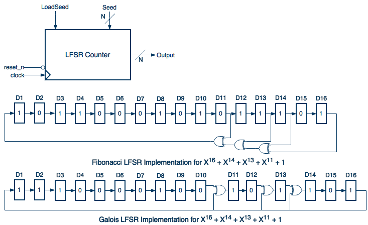
The LFSR (Linear Feedback Shift Register) counters cycle through the N-bit value space in a pseudo-random manner. LFSRs do not enter an overflow or underflow state.
The main use cases for LFSRs are N-bit pseudo-random number generators and pseudo-random bit sequence generators (e.g. test pattern generators, bit-stream (de)scramblers)
One option is to cover all possible values of the output values and seeds, but this is not practical with long sequence LFSRs (e.g. N=32). In order to reduce the value space you need to take the implementation details into consideration. Below I illustrate the implementation of a 16-bit LFSR in both Fibonacci and Galois forms (the seed load mechanism is not depicted):

For the above implementations you only need to check the following:
- seed 16’b0 produces a constant 16’b0 output for an indefinite number of clock cycles (you can check the output for N+1(17) clock cycles after the seed is loaded)
- non-0 seeds are loaded correctly (i.e. they are visible on the output after one clock cycle)
- output is constant and equal to the seed as long as the load signal is asserted
- the output is calculated correctly for at least N+1 (e.g. 17) cycles after the seed is loaded
The seed is the only control you have over the operation of the LFSR, which means it is the parameter of interest for coverage. Given the checks above you will only need to cover '0' and 16 ‘non-0’ seed values in a power-of-two range:
covergroup seed_cg with function sample(bit[WIDTH-1:0] x, int position);
   seed : coverpoint position iff (x == 0 || x[position-1]==1 && ((x&(~((1<<(position))-1)))==0)) {
      bins zero = {0};
      bins b[] = {[1:WIDTH]};
   }
endgroup

function void sample_seed(bit[WIDTH-1:0] x);
   if (x == 0) begin
      seed_cg.sample(0, 0);
      return;
   end
   for(int i=0;i<WIDTH;i++)
      seed_cg.sample(x, i+1);
endfunction
This sets the valid space to only 17 values, compared with the 65,535 values for the physical space. If you run 17CC for each seed it will give you a total of 289CC, which is much lower than 65535*17CC.
Sampling Time: every clock cycle after the seed is loaded.
Bit Stream Counter Value Coverage
You can use a counter to create a bit-stream instead of an integer value. Given the output is only 1-bit wide you can use the bit toggling coverage provided by the simulator instead of a dedicated coverage item.
For bit-streams that are periodic you need to check that:
- the output signal has the correct shape
- the output signal has the correct period
- the shape for one period repeats itself over and over
In terms of coverage you should target the parameters that control the shape and/or the period of the signal. For example a frequency divider can have an input that controls the division factor, so you need to cover all legal division values.
If the bit-stream is not periodic and is not affected by any of the counter’s inputs, than there is nothing else to cover regarding the bit-stream.
Notes
- Simulators can automatically cover the execution of a check ( i.e. immediate assertion). So even if there is no value to cover for a specific feature you'll still be able to tell if the feature was verified just by looking at the functional coverage report.
- The physical space of an N-bit integer value is a set containing all values that can be represented by the N-bit vector and has a size of 2^N-1 values. The valid space of an N-bit integer value is a subset of (and sometimes overlapping with) the physical space that contains only the values that are relevant in the context in which the value is used.
- In general, checking and coverage should be performed as a package: you always cover a value right after the check enssures its correctness.
- When talking about functional verification you should keep in mind that you have a limited number of simulation clock cycles at your disposal. Every time you define a coverage item try to estimate how many clock cycles are required to cover the item in ideal conditions (i.e. in a simple standalone environment). If the number of clock cycles seems large, try to reduce the valid space by taking into account some of the implementation details.
Further Study
You can learn more about the implementation of and principles governing digital counters from the following sources:
- Wikipedia page on Digital Counters
- Wikipedia page on Ring Counters
- Wikipedia page on Linear-Feedback Shift Registers
- Wikipedia page on Gray codes
- Cascaded Counters
- Neso Academy’s videos on Digital Electronics
- Theory of LFSR registers
I used Wavedrom to create waveforms and draw.io to create diagrams that appear in this article.
2 Responses
Great article!
You leave out Cellular Automata counters, of which LFSR is one.
For each display line, silently roll ahead as many iterations as the
width of your register. This avoids cluttering the display with bits
that are shifted copies.
48 bits long with one simple XOR works well to illustrate the point.
Three XORs seen at Wikipedia works too, but do try the simplified
rule first.
Example in FUZEBasic
REM *** Fibonacci Linear Feedback Shift Register ***
REM *** Immediate copy bits omitted from display by allowing ***
REM *** an entire register width to quietly roll unseen ***
DIM LFSR(49)
FOR X = 1 TO 49 LOOP
LFSR(X) = 1
REPEAT
FOR Z = 1 TO 28 LOOP
FOR X = 2 TO 48 LOOP
PRINT LFSR(X);
REPEAT
PRINT LFSR(49)
FOR Y = 1 TO 48 LOOP
FOR X = 1 TO 48 LOOP
LFSR(X) = LFSR(X + 1)
REPEAT
REM *** The default Pseudorandom feedback rule from Wikipedia ***
REM *** LFSR(49) = LFSR(1) XOR LFSR(3) XOR LFSR(4) XOR LFSR(6) ***
REM *** Simplified feedback rule to better illustrate a point ***
LFSR(49) = LFSR(1) XOR LFSR(3)
REPEAT
REPEAT