AMIQ released the Physical Coding Library on GitHub.
The Physical Coding Library provides SystemVerilog/UVM implementations of line coding schemes that are common to all major high speed communication protocols: Ethernet, RapidIO, DisplayPort, SATA, USB3.0, PCI Express etc. These are the supported line coding schemes:
- 8b/10b encoding
- 64b/66b encoding
- additive scrambling with parameterizable LFSR
- multiplicative scrambling with parameterizable LFSR
The library also includes documentation, self checking tests and usage examples.
The Physical Coding Library is available to the verification community for free under the Apache License 2 so feel free to download, use and contribute.
In the following sections I will briefly present the following topics:
- Line Coding
- DC Balancing
- Clock and Data Recovery
- Error Detection
- Communication Line Management
- (De)Scrambler
- Physical Coding Library description
1 Line coding
Coding schemes are used by data communication protocols to protect against data corruption and to adapt to the physical properties of the medium used to exchange data. Line coding is a process applied on digital data to produce a new representation of it, adapted for transmission through the physical medium (e.g. coaxial cable, twisted pairs, optical fiber). Desirable physical qualities of a signal carrying information through a serial line are DC balance and high transition density (to help with clock and data recovery). Establishment and maintenance of communication between two ends of a serial line require transmission of additional control information. To further increase reliability line coding mechanisms also support error detection, handling and reporting.
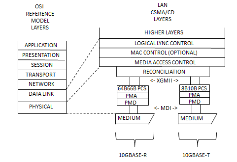
In case of high speed communication protocols the line coding is implemented by the Physical Coding Subsystem at Physical Layer Level of the OSI stack as described in IEEE802.3 standard:

Examples of such line codings are: 8b10b, 64b66b, Manchester, RZ(return to zero), NRZ (non return to zero).
1.1 DC Balancing
A DC balanced signal has a zero continuous component for a given time window. In the context of digital data transmission on a serial line, DC balancing is reached if the serial line is being held in both high and low voltage levels for a statistically equal amount of time. From the digital perspective, this means that the number of ones in the data bit stream equals that of zeros. The picture below shows the cases of balanced and unbalanced signals.

Usually the bit stream intended for transmission is not DC balanced. Thus, it is a necessity for the data to be encoded. Depending of how they solve the DC balancing requirement, codes can have constant-weight or paired disparity (e.g. 8b10b), the second being widely used in high speed communications. For codes that don’t intrinsically fulfill the DC balance requirement (e.g. 64b66b) a scrambler can be used to change the coded bit-stream statistics.
The Physical Coding Library provides implementation of both 8b10b and 64b66b coding schemes.
1.2 Clock and Data Recovery (CDR)
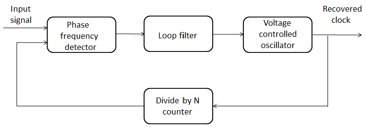
Typically, when sending data through serial transmission lines, clock and data information are embedded in one signal in order to decrease the wiring and, consequently, crosstalk. The receiver needs to recover the clock out of the line signal, in order to be able to reconstruct the correct data. For this purpose, the receiver uses a phase lock loop oscillator (also referred as PLL) that generates an approximate reference clock and aligns the phase of the reference clock to the transitions of the incoming signal. Below you can see a block diagram of such a PLL oscillator.

In order to be efficient, the clock recovery process requires frequent transitions in the received signal which are best achieved when the number of ones and zeros are equal over a given window of time. Coding schemes as the ones mentioned in DC balancing section create a new representation of the data stream that it is suitable for clock recovery.
The Physical Coding Library does not provide an implementation for clock and data recovery unit. For digital simulation purposes it is not mandatory as long as the transceiver and receiver clocks are aligned.
1.3 Error Detection
The data transmission is an inherently error-prone process due to: the physics of the materials involved, noise, transmission line cross-talk, transmission line impedance mismatch between the line and the receiver or driver etc. This makes error detection an essential feature that must be embedded in the transmitted signal, allowing the receiver to detect possible errors. Coding schemes provide this by use of redundancy – increase in the number of bits used to represent a data unit. This is an inevitable compromise that decreases user data bandwidth in order to increase reliability.
For example in case of 8b10b the data unit of 8bit is increased with 2 bits, which means it reduces user data bandwidth with 20%. For 64b66b the user data bandwidth is reduced with approximately 3%. The amount (i.e. 20% or 3% above) of decrease in user data bandwidth due to encoding is also known as encoding or protocol overhead.
The Physical Coding Library provides support for the following types of errors:
- running disparity
- symbol errors
1.4 Communication Line Management
Redundancy allows coding schemes to define unique bit sequences, referred to as characters or symbols. There are two types of symbols:
- data symbols: encode user data
- control symbols: encode control data which is passed through the physical link between data link layers.
The control symbols provide support for the line bring-up procedures (i.e. lane initialization, lane alignment), line maintenance, retransmission etc. These procedures are implemented at the data link layer level and since the communication line management differs from protocol to protocol the Physical Coding Library does not provide implementations of bring-up procedures.
2. (De)Scrambler
Scramblers are used to increase the density of transitions in the line signal. The scrambler is used on the transmission side while the descrambler is used on the receiving side.
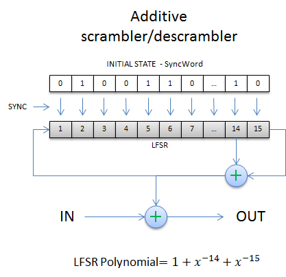
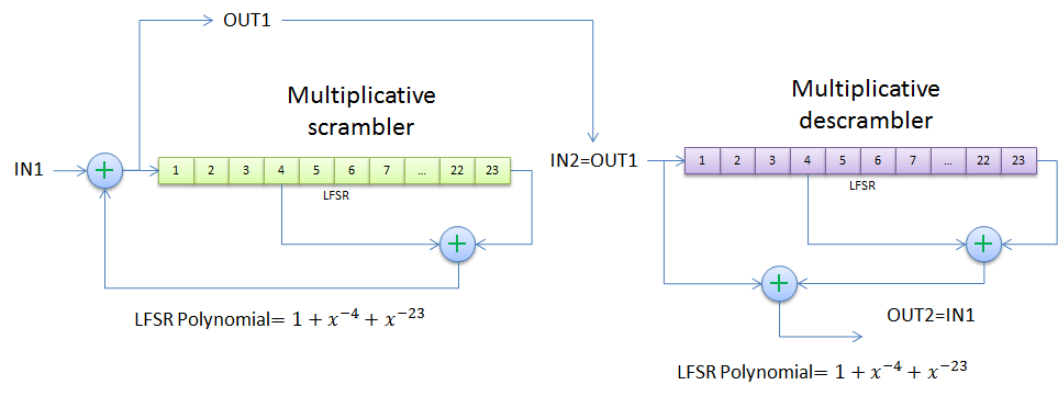
There are two types of scramblers: additive, also called synchronous, and multiplicative or self synchronizing scramblers. Scramblers/descramblers of both types are generally implemented as linear feedback shift registers(LFSR) and they are determined by the polynomial of their LFSR.


Contrasting their multiplicative counterparts, that do not require an initial LFSR state to be set, additive scramblers need to be loaded with a synchronization sequence prior to starting operation on an input bit stream.
The Physical Coding Library contains implementations of both multiplicative and additive scramblers with parameterizable LFSR.
3. Physical Coding Library
The Physical Coding Library is a package written in SystemVerilog and UVM compliant, which includes the following:
- endec_8b10b – an 8b10b encode/decode package
- endec_64b66b – a 64b66b encode/decode package
- scrambler_descrambler – an additive and a multiplicative scrambler/descrambler package
3.1 endec_8b10b package (8b10b encoding scheme)
The package contains the implementation of an encoder and a decoder along with coverage definitions. The path of the package file relative to the project directory is:
physical_coding_library/encoder_decoder/sv/endec_8b10b/endec_8b10b_pkg.sv
The encoder/decoder and coverage collector classes can be instantiated under any uvm_component-inherited class of the verification environment.
3.1.1 Data item
The coder and encoder functions make use the endec_8b10b_enc_in_dec_out_s data structure:
// serves as input of the encoder and output of the decoder
typedef struct {
// 8 bit value input for encoding
// or output of decoding
bit [7:0] enc_dec_8b_val;

// field indicating if it's data or control symbol
bit is_k_symbol;

// used to register decoding errors
// 0 - no error
// 1 - disparity error
// 2 - symbol error
bit [1:0] decode_err;
} endec_8b10b_enc_in_dec_out_s;
It defines an 8-bit field for the value to be encoded or the output of the decoding, a 1-bit field indicating if it’s a data or a control symbol and a field used to flag decode errors.
3.1.2 Encoding
To encode an 8-bit input data, the encoder class (endec_8b10b_encoder) provides the encode() function that has the following signature:
virtual function bit [9:0] encode (endec_8b10b_enc_in_dec_out_s a_encode_in);It accepts as input a struct of type endec_8b10b_enc_in_dec_out_s and outputs the encoded 10-bit symbol.
3.1.3 Decoding
To decode 10-bit symbols, the decoder class (endec_8b10b_decoder) defines the decode() function with the following signature:
virtual function endec_8b10b_enc_in_dec_out_s decode (input bit [9:0] a_coded_symbol);It accepts as input a 10-bit coded symbol and outputs the struct holding the decoded 8-bit data with the control/data symbol indication and the decode_err field which flags decoding errors.
3.2 endec_64b66b package (64b66b encoding scheme)
This package contains code for 64b66b encoder and decoder along with coverage definitions. The implementation follows the specifications in IEEE 802.3/Clause 49 standard. The package file relative to the project directory is:
/physical_coding_library/encoder_decoder/sv/endec_64b66b/endec_64b66b_pkg.sv
The encoder/decoder and coverage collector classes can be instantiated under any uvm_component-inherited class of the verification environment.
3.2.1 Encoding
The encoder class defines the encode() function to be used for the encode process and it has the following signature:
virtual function bit [65:0] encode (bit[71:0] a_xgmii_in);The encoding process operates on two XGMII type transfers. These are defined in IEEE 802.3/Clause 46 standard which introduces a media independent interface, abbreviated as XGMII. One such transfer consists of a 32-bit data input and a 4-bit input carrying information about the type of the 4 bytes contained in the first input, each bit corresponding to one byte. The aforementioned encoding function receives as input two such XGMII transfers concatenated into the 72-bits input.
The result of the encoding process is a 66-bits coded block explained in IEEE 802.3/Clause 49 standard.
3.2.3 Decoding
The decoder class defines the decode() function to be used for decoding 66-bits encoded code-blocks and it has the following signature:
virtual function bit [71:0] decode (bit[65:0] a_coded_block_in);It accepts as input the coded 66-bit code-block and returns a 72-bits output holding the information for 2 XGMII type transfers(identical to the input of the encode function).
3.3 scrambler_descrambler package
This package contains implementations for additive and multiplicative scramblers and descramblers. Users of the package can define the LFSR polynomial (order and taps) via class parameters.
The scrambler and descrambler of the additive version have the same implementation. Thus, the package contains only one class used for implementing both functions. For the multiplicative flavor, the implementation varies between the scrambler and descrambler so two classes are defined.
Creating and using a specific scrambler/descrambler LFSR is easily achievable by setting LFSR parameters in the encoder or decoder class.
3.3.1 Additive scrambler/descrambler
Both scrambler and descrambler are implemented by the same class(scrambler_descrambler_additive). The class is parameterized to allow flexibility in choosing the order and taps of the scrambler/descrambler LFSR polynomial. Below is an example instantiating a scrambler defined by the LFSR polynomial: (x^63 + x^49 + 1) :
// the scrambler and descrambler classes are actually the same
// scrambler instance
scrambler_descrambler_additive#(64, 'h8001000000000000) m_add_scrambler;

// descrambler instance
scrambler_descrambler_additive#(64, 'h8001000000000000) m_add_descrambler;
Before performing any scrambling/descrambling an initial, non-zero, state must be set for
the LFSR by calling the member function:
virtual function void load_lfsr (input bit[ORDER-1:0] a_load_value);The scrambling/descrambling operation is done by calling member functions :
virtual function bs_t scramble (input bs_t a_bs_in);and
virtual function bs_t descramble (input bs_t a_bs_in);which takes as input a bit-stream(i.e. typedef bit bs_t[]) and outputs the scrambled/descrambled bit-stream.
3.3.2 Multiplicative scrambler/descrambler
For the multiplicative case the scrambler has a different implementation than the descrambler so two classes are defined. Both classes are parameterized to allow any LFSR polynomial similar to the additive case. Example of a multiplicative scrambler/descrambler pair instance is given below:
// scrambler instance
scrambler_multiplicative#(64, 'h8001000000000000) m_mult_scrambler;

// descrambler instance
descrambler_multiplicative#(64, 'h8001000000000000) m_mult_descrambler;
There is no need for state initialization of the LFSR in this case, the scrambling/descrambling operation is performed by a call of the member functions:
virtual function bs_t scramble(input bs_t a_bs_in);and
virtual function bs_t descramble(input bs_t a_bs_in);The above functions take as input a bit-stream and return the scrambled/descrambled bit-stream.
References
OSI Model
Coding Theory
Digital Transmission – Line Coding
IEEE 802.3
IEEE 802.3 Architecture and 40/100GbE
Phase Locked Loop
Scrambler
Xilinx Aurora 8b10b Protocol Spec
High-Speed Serial I/O Made Simple