
Introduction
This work addresses the inability to reproduce, port, or shorten a UVM test failure outside of the exact seed, simulator, and testbench that originally produced it — by replaying the recorded stimuli from a waveform instead of re-randomizing them.
Table of Contents
Problem
In Constrained Random Coverage Driven Verification (CRCDV), UVM achieves deterministic test replicability by initializing the Pseudo-Random Number Generator (PRNG) with an integer seed. This seed drives the randomization and hashing algorithms that resolve rand variables throughout the simulation. However, the specific implementation remains strictly dependent on the simulator and its exact version.
Stimulus generation is therefore strictly dependent on three core variables: the seed, the simulator, and the Verification Environment (VE). This tight coupling introduces significant debugging bottlenecks, primarily manifesting in two critical challenges:
- Environment Dependency: The inability to isolate and replay block-level failures discovered during subsystem-level tests directly within a dedicated block-level VE.
- Temporal and Seed Dependency: The severe inefficiency of debugging long-running tests that fail late in the simulation timeline, which traditionally forces the engineer to bypass the PRNG overhead by manually authoring directed tests.
Solution
Wave2Stim (W2S) is an architecture designed to decouple stimulus generation from these inherent UVM dependencies. The following sections detail its architectural framework and practical utility in addressing these verification bottlenecks.
W2S uses a VCD file from a prior test in order to replay the stimuli at the saved timestamps. Consequently, tests can be ported across simulators & testbenches, and can be shortened.
Notably, the tool does not replay the outputs; the RTL and the UVM environment remain unaware that it replays the inputs rather than generating them.
Use cases:
The previously mentioned debugging challenges inspired four main use cases that guided the tool’s design:
- Simulator migration;
- Testbench migration;
- Subsystem to block porting;
- Test fragment (shortening a test).
Architecture
The W2S architecture comprises three primary components: a SystemVerilog package containing the core test classes (which must be included during compilation), a compiled C++ library leveraging VPI and DPI-C, and a Python GUI built with the PySide6 framework [1].
The architecture can be split into four layers, as seen in Figure 1.
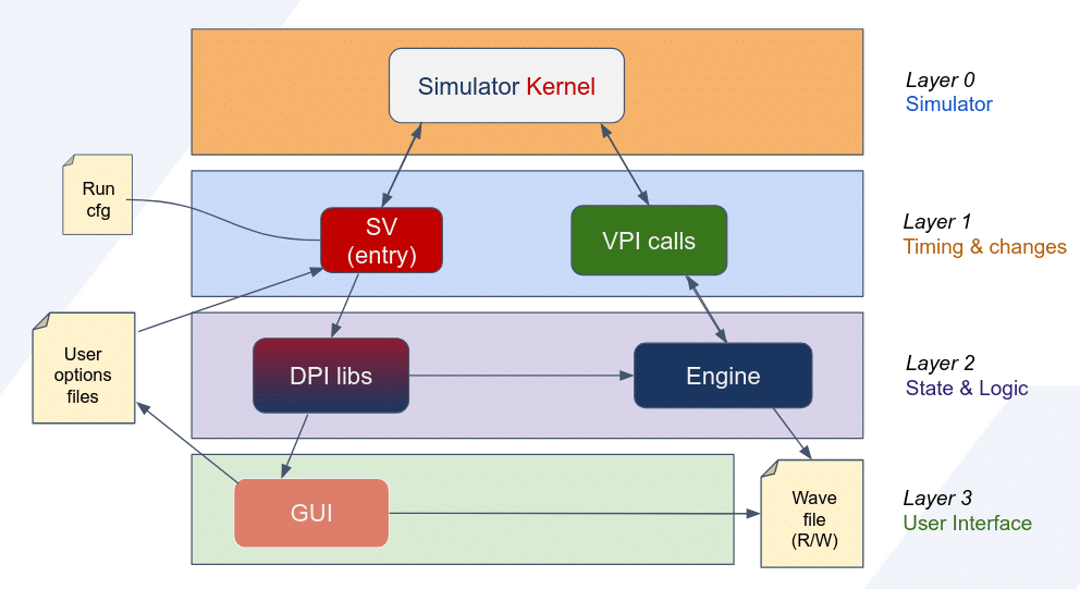
Figure 1: W2S Architecture Overview
Layers
0th is the Simulator Kernel, which is treated as a black box with which only SystemVerilog and VPI interact.
1st manages timing and value changes, via SystemVerilog time delays (ex: #10) and VPI value change calls (vpi_put_value).
2nd encapsulates all state management and core logic, within the C/C++ engine. The entry point of the flow is via DPI-C functions, which call the engine class functions for implementation, as seen in Figure 2.
3rd integrates user interfacing via the GUI. It contains the automatically opened Python GUI when information is missing.
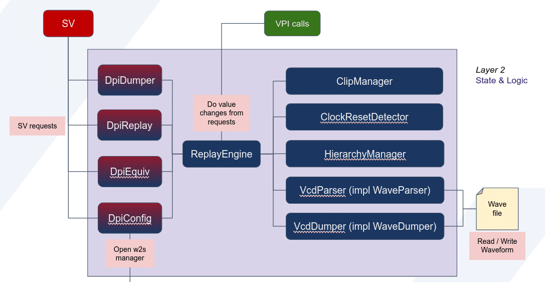
Figure 2: Layer 2 introspection
Implementation details
The architectural framework and the corresponding design decisions guiding the development of Wave2Stim are detailed in the subsequent subsections.
Input Selection
When extracting data from a VCD, the environment must separate the inputs from other registers, in order to replay the inputs and allow RTL response on the outputs. Initially, the target signals were manually selected and passed by the user via uvm_config_db. As this became too verbose, the W2S methodology has evolved to simplify this setup process:
- Interactive GUI: Introduced in order to reduce manual entry. This feature pauses the simulation at time zero, allowing the user to select the input signals by clicking rather than writing full paths.
- Automated Inference: The process is now fully automated. Before consuming any simulation time, the environment generates a zero-time VCD dump. This VCD contains $comment statements that describe the register connections, allowing the tool to automatically identify the inputs without user intervention.
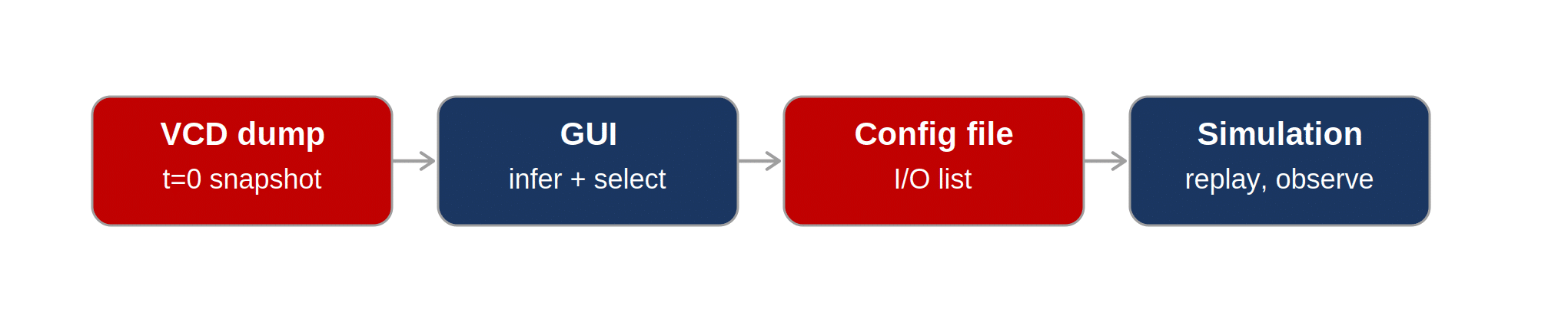
Figure 3: Input Selection Flow
Reflection
Parsing a stimuli VCD in SystemVerilog allows for the construction of a data structure, such as a map linking signal names to their replay values. However, applying the value requires a direct memory reference rather than just the signal’s string identifier.
Reflection allows for getting a reference of a variable by using its name. Since SystemVerilog lacks native reflection capabilities, the responsibility to change the signal values is delegated to VPI.
VPI / DPI-C
VPI (Verilog Procedural Interface), also known as PLI (Programming Language Interface) by older references, is a C library that allows signal manipulation using runtime strings, running functions (callbacks) at specific moments in the simulation, design hierarchy and post-parsing static code analysis (e.g.: entering an initial…begin block to search for all continuous assignments).
DPI-C (Direct Programming Interface with C) allows for declaration of functions in SystemVerilog with implementation in C/C++. This feature is important because it links the architecture built in SV with the features that VPI provides.
Both VPI and DPI-C are standardized in IEEE 1800 [2], the document that defines the SystemVerilog standard. This standardization ensures that all major simulators support these interfaces, rendering the solution portable.
Hierarchical Parsing
To enable automatic input selection inference, W2S treats the entire testbench as a black box, in order to determine whether a signal is an input (injection point). To achieve this, it evaluates each input of the RTL and traces upward in the hierarchy until there is no upper connection or continuous assignment.
While verifying if there is an upper connection is straightforward with VPI, the continuous assignments are checked against a prebuilt list using static code analysis.
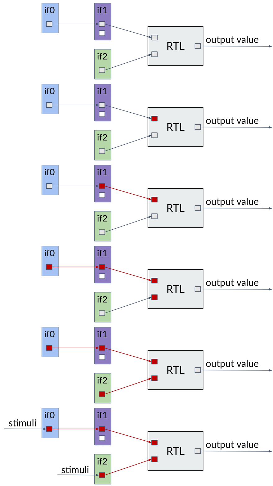
Figure 4: Injection point detection
Timing & Assignments
While the values of the signals are important to replay, it is also crucial to apply them at the correct timing. Given that the signals originate from a uvm_driver in the original test, they are typically driven as non-blocking assignments (NBA).
In order to drive signals as non-blocking with VPI, the process must be delayed to the NBA region of the timestamp.
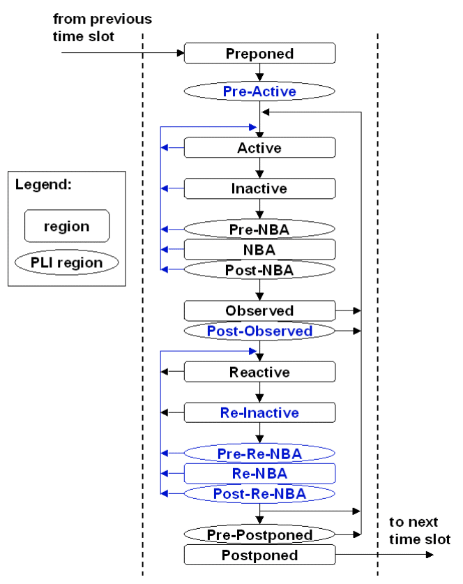
Figure 5: Accelera standard for timestamp event scheduling [3]
Whenever there are changes in the NBA (or post/pre regions), they are transitioned into the Active region and are executed simultaneously, creating a new delta-cycle. W2S uses Post-NBA (cbReadWriteSynch) to modify the values of the signals.
Other regions have different roles, for example Inactive is a state that explicitly processes simulated non-blocking assignments in older versions of Verilog (e.g., a = #0 b). The Reactive region serves the verification environment by ensuring clock-synchronized assertions wait for all the combinational values to settle first, then react to the new set of values.
Signal mapping
Porting a test across different testbenches frequently introduces signal name mismatches. For this reason, a mapping process is required.
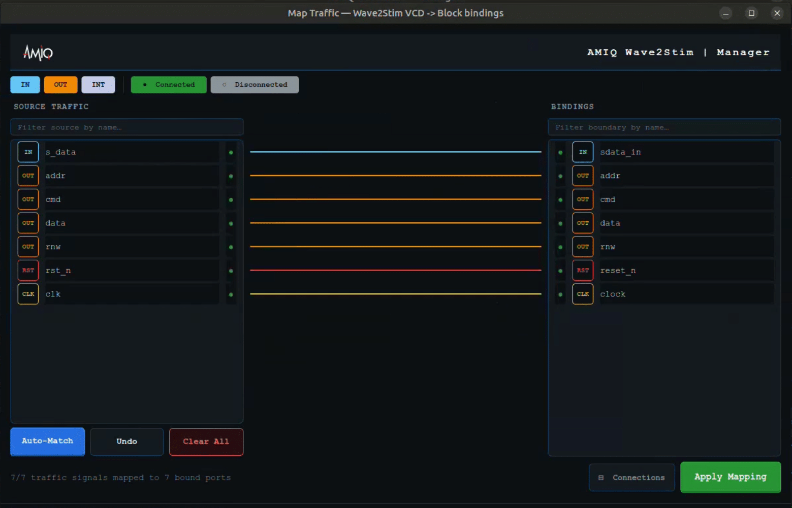
Figure 6: Mapping window
To map an input, W2S identifies its corresponding RTL port binding, before and after porting to another testbench. Given that the bound RTL port remains identical across both testbenches, the mapping is inferred via transitive composition.
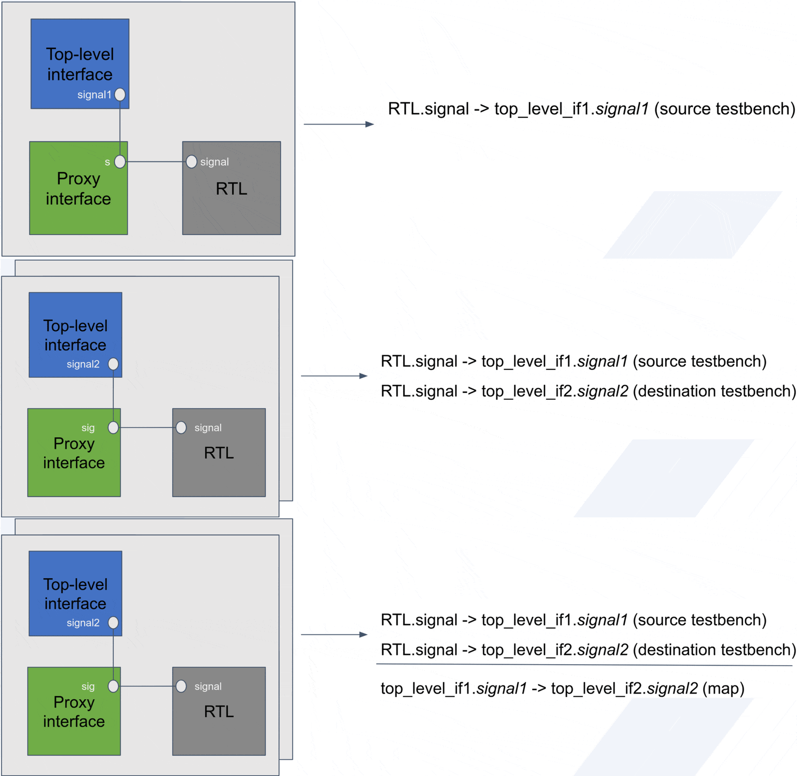
Figure 7: Mapping process
Timescale adjustment
While a testbench runs at a certain timescale, input VCD files can be written in a higher or lower timescale. For that reason, W2S detects this, warns the user of possible precision loss, and adjusts the time difference.
To find the adjusting factor, it exploits the SystemVerilog time variable type, which can hold unit-specified amounts of time – for example 1 second. Depending on the declared timescale of the testbench, the underlying value of the time variable contains the number of units of the current timescale.
Leveraging this intrinsic property, W2S can cast the time variable to longint and compare against a floating point literal, obtaining a factor of time adjustment. This factor is then passed to every SystemVerilog component that consumes time for the replay mechanism.
Record feature, w2s_test
The W2S recording mechanism optimizes waveform output by excluding unused signals and eliminates the need for manual testbench modifications, such as inserting $dumpvars directives. To achieve this, a custom-built VCD dumper class directly dumps the waveform via VPI.
To easily integrate this functionality, the framework provides a w2s_test wrapper. This class dynamically inherits the user’s target test via a compile-time +define argument, centralizing all W2S recording and replaying infrastructure into a single entry point. However, to guarantee that this wrapper generates identical stimuli for a given seed as the original standalone test, the architecture must strictly address the concept of random stability.
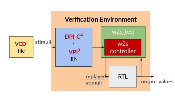
Figure 8: Integrated w2s_test
Random Stability
Random stability refers to the predictability of pseudo-random stimulus generation and how structural changes to the testbench impact it. Maintaining random stability during w2s_test recording is essential to successfully capture the exact test the user originally intended to replay.
UVM generates stimuli by assigning Pseudo-Random Number Generators (PRNGs) to each randomizable object. A PRNG is an algorithm that, given a seed, generates seemingly random numbers. This mechanism ensures reproducibility, as identical seeds yield identical pseudo-random sequences.
UVM assigns PRNGs to randomizable entities hierarchically. Randomizable entities include modules, processes, and items with randomizable fields. Each child takes its seed from the parent’s next available value, as seen in Figure 9. If multiple children exist, they sample the parent’s PRNG in order.
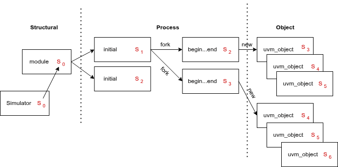
Figure 9: Random Stability via testbench hierarchy [4]
In order to respect the original test’s hierarchy, W2S inserts itself as an isolated branch after user test creation by inheriting it. It also avoids creating any randomizable entities until after the user’s test has fully initialized.
Configuration Files & Plusargs
The plug & play, automatic philosophy introduced with w2s_test required more and more configuration plusargs. They can control the replay or record VCD path (absolute or relative to $PROJ_HOME, automatically inferred by presence or absence of a leading slash), the activation of replay or record, fallback behavior if replay fails during the configuration phase, among other parameters.
To address the increasing verbosity of run commands, the framework now supports run configuration files. Instead of requiring multiple plusargs, the execution needs only one: the path to the file containing all plusargs of interest. This path can be absolute or relative to $PROJ_HOME; if no specified config exists in $PROJ_HOME, the script searches among the default ones inside $W2S_ROOT. Furthermore, configuration files eliminate the need for the leading AMIQ_W2S_ prefix on plusargs, which the tool originally required to prevent overriding user-defined plusargs.
Clock Optimization & Alignment
Saving a clock signal’s values is very inefficient for both the occupied memory and the replay mechanism, as it needs to bypass many timestamps that have no other traffic than the clock. For this reason, clocks are excluded from the VCD.
However, excluding the clock meant that sometimes, when porting between testbenches, the clock would differ. Consequently, the user is responsible for ensuring the clock is behaving identically to the prior test.
Although the tool initially relied on manual selection, subsequent updates equipped it with an automated clock and reset detection mechanism.
Clock & Reset Detection
Hierarchy parsing is also highly effective for identifying asynchronous signals (clock, reset, and async set). The tool scans the RTL for @(posedge/negedge) blocks to detect asynchronous signals, marking the extracted signal names as possible targets of interest.
The tool fully automates the process of determining whether a signal acts as a clock, reset, or another control signal only if W2S recorded the test. An external VCD does not contain enough information to deduce the role of the signal. In that case, the GUI would suggest roles based on the name and ask the user to confirm each detected candidate.
When recording with W2S, the tool evaluates several characteristics for each candidate:
- Periodicity
- Long idle
- Influence on other signals
Differentiating between a clock and a reset/set signal primarily relies on periodicity. Once the system identifies a signal as periodic, it writes the signal metadata as a $comment in the recorded VCD, detailing the period, duty cycle, start offset, and start value.
Between set and reset signals, the W2S tool focuses exclusively on the global reset signal. Asserting the global reset immediately drives multiple signals to a known state (typically 0), unlike an asynchronous set that usually modifies a single signal.
To extract the polarity of this global reset, the analysis engine compares the idle time with the assertion time, since global resets typically feature a much shorter assertion period than their inactive state.
Test fragment
The test fragment use-case involves extracting a subset of stimuli. It is activated by a plusarg, which triggers the GUI to ask the user to mark this subset.
The tool replays the extracted stimuli from an idle state of the RTL, which necessitates identifying the global reset signal. This ensures that the testbench asserts the reset for several clock cycles to guarantee an initialized RTL state prior to simulation. In any other use case, the system treats the reset signal as a standard input.
As an experimental feature, the tool supports chaining replayed timeframes. Random/Idle sequences can also be chained.
Results
Performance and optimization
The project underwent a performance analysis, demonstrating an increased simulation overhead by approximately 58%. While performance was not an initial R&D priority, this metric highlighted a key area for optimization.
To analyze the performance improvement, five versions of the tool were considered:
- unoptimized: The unoptimized, raw version
- mmapped VCD: Improved VCD Parsing by implementing an optimistic Producer-Consumer architecture and mapping VCD chunks to RAM, as seen in Figure 10.
- signalId: Assigning numerical IDs to the signals and only referring to them by ID in order to maximize cache hit and minimize string parsing
- 1 dpi call per update: Minimizing SV/C++ context switching by batching value modifications into a single API call, rather than issuing individual calls per signal.
- memory prealloc: Minimizing the heap allocations by having a preallocated memory zone that grows when necessary.
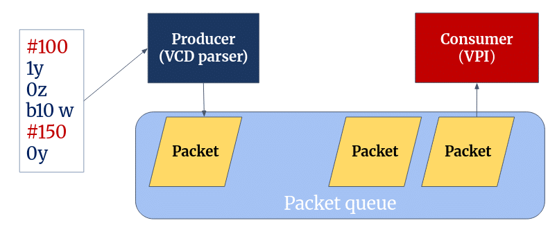
Figure 10: Producer-Consumer architecture
Table 1 provides an overview of how each incremental variant decreased the elapsed real execution time of a replayed test. Figure 11 plots the results in an illustrative graph.
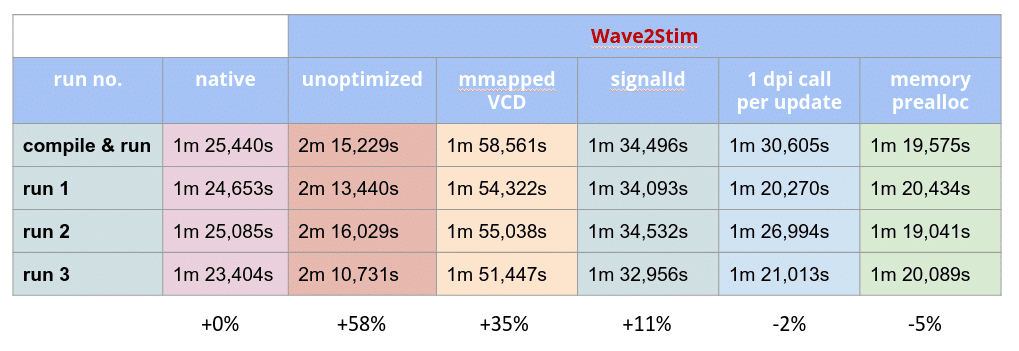
Table 1: Incremental optimization results
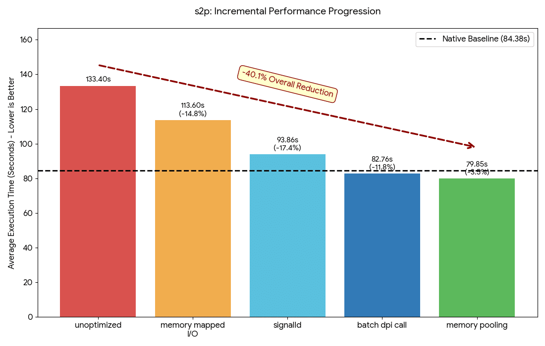
Figure 11: Visualization of overall optimization
The optimizations were substantial, resulting in a ~40% overall reduction in time needed to run a replayed test. The dotted line in the graph represents the native line of performance. This experiment surpassed the line, indicating parsing and replaying was a faster process than generating the stimuli.
Tool validation environments
Multiple proprietary and open-source testbenches served as evaluation targets for the replay tool.
As proprietary testbenches, two equivalent variants of a multiplier block verified testbench migration. A multiplexer block validated the test fragment, along with an encryption subsystem consisting of 5 blocks for the subsystem to block porting.
On the open source side, uvm_ref_flow [5] provided the environment to verify the simulator migration use case, specifically with the spi_simple_test, based on the SPI protocol.
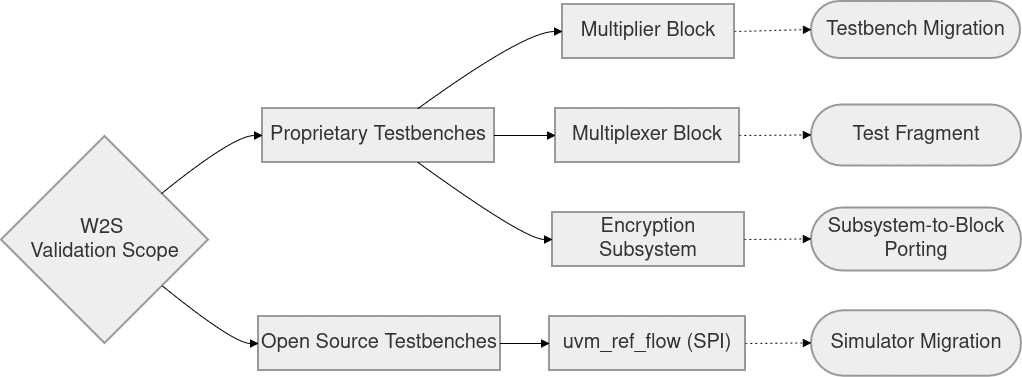
Figure 12: Visualization of overall optimization
Equivalence checking
To verify that the replay process was accurate, a need for an automatic self-checker arose. For this reason, a VCD equivalence function was developed, automatically invoked during the check phase. The equivalence checker compares the original stimulus VCD against the VCD generated during the replay process, resulting in one of four possible outcomes:
- Equivalent;
- Non-equivalent;
- Equivalent, but with missing information about one or more signals;
- Non-equivalent, also with missing information about one or more signals.
Limitations
While W2S successfully addresses multiple verification bottlenecks, certain edge cases remain beyond its current scope. Known limitations of the tool are listed below.
Dynamic Clocks & Double Data Rate (DDR)
W2S assumes a clock starts at an offset and then is periodic for the rest of the simulation, sampling on one edge of the clock. However, this assumption does not fully account for reality; in practice, gated clocks and dual-edge sampling are common.
While these scenarios were not explicitly evaluated, the tool may still function for use cases that avoid automatic clock and reset detection, which excludes the test fragment use case.
Inout RTL ports
A port functioning as both an input and an output completely disrupts the input selection process, as the tool no longer knows which signals it must drive and which it must observe. Using another dump format that supports driving direction, such as EVCD, could solve this issue.
Calculated or Composed ports
While the hierarchical lookup mechanism accounts for several complex corner cases (such as when a port operates as an interface rather than a register), it fails to locate the root driver of an RTL input port if an expression calculates that input from two other values. Figure 13 demonstrates this scenario.
A further limitation arises when a bus comprises multiple sub-buses, as Figure 14 illustrates.
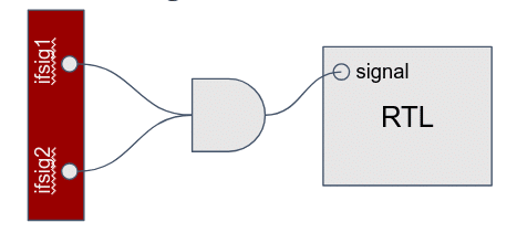
Figure 13: Calculated RTL port
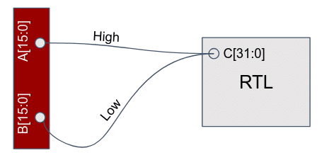
Figure 14: Composed RTL port
Conclusions
Wave2Stim (W2S) decouples stimulus generation from UVM dependencies, offering a deterministic, VCD-driven replay mechanism using VPI and DPI-C. Designed as a plug-and-play solution, the tool efficiently supports simulator migration, testbench migration, subsystem to block porting, and test fragmentation. Furthermore, architectural optimizations enabled the replay process to approach native stimulus generation performance, while guaranteeing data accuracy through an automated equivalence checker.
Future improvements can expand W2S to support bidirectional ports, composed RTL ports, and dynamic clocks. By enabling engineers to port and replay specific simulation timeframes without modifying the original testbench, this methodology eliminates major debugging bottlenecks and significantly conserves computational resources.
References
[1] – PySide6: https://pypi.org/project/PySide6/
[2] – IEEE 1800-2017 Standard for SystemVerilog – Unified Hardware Design, Specification, and Verification Language (VPI/DPI: Chapters 35-38, Annexes H, I, K, M): https://ieeexplore.ieee.org/document/8299595
[3] – SystemVerilog Event Scheduling Semantics: https://www.accellera.org/images/eda/sv-ec/att-4051/Event_Scheduling_20070205a.pdf
[4] – SystemVerilog Random Stability: https://www.doulos.com/media/1293/snug2013_sv_random_stability_paper.pdf
[5] – UVM Reference Flow 1.1: https://forums.accellera.org/files/file/70-uvm-reference-flow-version-11/
Repository
W2S files are available on the public AMIQ Consulting GitHub page. It includes the open-source uvm_ref_flow testbench example and screenshots showcasing the results on proprietary testbench code.
Acknowledgements
This project served as the bachelor thesis for the writer, Georgian Sofronea.
I would like to thank AMIQ Consulting for the mentorship and support in elaborating this thesis, especially to my mentors during this 9 month long process:
Edane Ibram,
Dragoș Dospinescu,
Ana Cristescu.
I would also like to acknowledge the reviews and suggestions provided by other colleagues at AMIQ Consulting and AMIQ EDA that led to the final form of this thesis.
Thank you.