You can download the code from the AMIQ GitHub repository.
A Design under Test (DUT)
The DUT is a subsystem that contains a parameterizable number of identical processing units (PUs), like the one in the figure below:

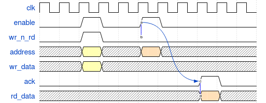
Each one of the PUs provides a bus for local RAM access. All RAM busses are identical and follow the same basic protocol:

In my implementation, all the RAM blocks are accessed at the same time using the same type of command (e.g. read or write) and the data written to or read from memory can be different. This should translate into a simultaneity check that ensures accesses to all busses happen at the same time and are of the same type.
My design is a simplified version of a more complex design that could be parameterized by 5 parameters. For the sake of simplicity, I kept only the rd_data/wr_data signal width parameter (i.e. RAM_WIDTH).
About VIP Architecture and VE Topology
Given the large amount of parameters, it is useful to protect the VIP/VE from parameter creep: parameters that propagate in all corners of the VIP and VE without bringing too much value. This can be achieved using an accessor class.
Given that all RAM instances are accessed at the same time, I have two options available to me regarding the VE topology:
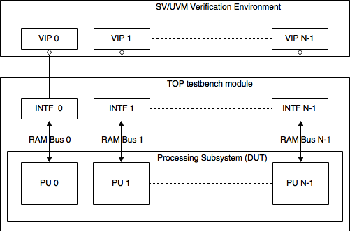
- One VIP instantiated multiple times (i.e. N times, one for each processing unit instance)
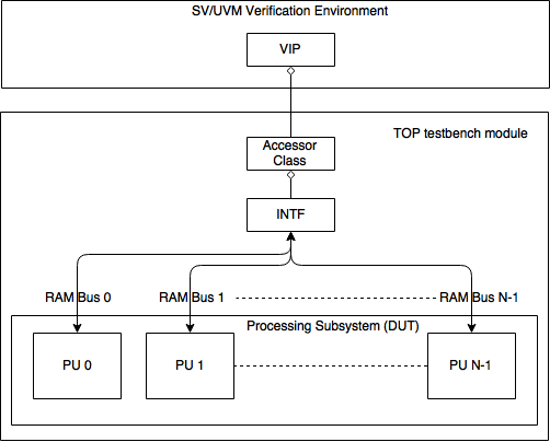
- One VIP instantiated only once with an extra parameter (i.e. N, the number of processing units)
The VIP architectures for 1) and 2) are described in the pictures below.
 Option 1) – VE topology that uses multiple VIP instances
 Option 2) – VE topology that uses a single VIP instance
There are pros and cons for both options. You should consider VIP and protocol use cases before choosing one or the other.
Option 1) uses fewer parameters, which comes at the cost of more threads running in parallel and makes it harder to check for bus access simultaneity. Option 2) adds an extra parameter to the interface while reducing the number of threads running in parallel and simplifying the checking of bus access simultaneity. Also, since option 2) hides the physical interface implementation it is more flexible when it comes to future interface enhancements.
Option 1) is probably the most used VE topology, so I won’t provide a detailed explanation of its implementation. I will explain option 2) in detail.
The Interface
Beside the existing parameter (i.e. RAM_WIDTH), you need to enhance the interface with one more parameter that specifies the number of PUs (i.e. PU_COUNT). Again you have two options: either a) declare a logic vector that includes the bits from all signals:
interface ex_if #(
  	int RAM_WIDTH = 16, // RAM Data Bus width
        int PU_COUNT = 7 // the number of Processing Units
   )(input clk, input rst);
   //  wr_data bus signal
   logic[((PU_COUNT * RAM_WIDTH)-1):0] wr_data;
   //  wr_n_rd bus signal
   logic[(PU_COUNT - 1):0]          	wr_n_rd;
endinterface
OR b) declare an array of signals (instead of a single long vector):
interface ex_if #(
  	int RAM_WIDTH = 16, // RAM Data Bus width
        int PU_COUNT = 7 // the number of Processing Units
   )(input clk, input rst);
   //  wr_data bus signal
   logic[(RAM_WIDTH-1):0] wr_data[PU_COUNT];
   //  wr_n_rd bus signal
   logic          	wr_n_rd[PU_COUNT];
endinterface
The example code on GitHub supports both versions (see ex_top.sv), so it’s up to you which one you use in your environment.
The Accessor Class
The accessor class is a proxy class between the physical interface and the agent accessing it. It is used to isolate the physical interface implementation details from the VE, while still providing the flexibility of parameterized behavior and allowing for future interface extensions (see the References section).
The accessor class contains the API that allows the agent to interact with the physical interface. This API uses setter tasks to drive signals (e.g. requires timing) and getter functions (e.g. the sampling is immediate) to retrieve the value of a signal. Besides the signal interaction API, the accessor class contains an API for:
- Parameter getters: retrieve the parameter values
- Utility functions: getters/setters for accessor class name, virtual interface, etc.
- Event handling: tasks that wait for specific events (e.g. posedge/negedge reset, posedge clock, etc.)
The accessor class is defined in two “steps”:
- Definition of the API within an abstract accessor class using either a virtual class or an interface class
- A parameterized implementation of the abstract accessor class
This example uses the virtual class-based implementation, but you can find both implementations on GitHub. The interface class is quite new in SystemVerilog and therefore may not be supported by your current simulator version.
// abstract accessor class; it is optional to inherit the uvm_object
virtual class ex_if_accessor_base extends uvm_object;
   function new(input string name="ex_if_accessor_base");
  	super.new(name);
   endfunction
   // implement methods that retrieve the parameters values
   pure virtual function int get_ram_width_p();

   // implement tasks that wait on specific events: posedge of clock, negedge of reset etc
   pure virtual task posedge_clock(int unsigned a_period=1);

   // implement setter tasks which drive the signals
   pure virtual task set_wr_data(l64_q_t data);

   // implement getter functions which read out signals
   pure virtual function l64_q_t get_wr_data();
endclass
The parameterized implementation of the abstract accessor class is:
class ex_if_accessor#(int RAM_WIDTH = 16, int PU_COUNT = 7) extends ex_if_accessor_base;
   // instance of virtual interface
   virtual interface ex_if#(RAM_WIDTH, PU_COUNT) vif;

   // constructor
   function new(input string name="ex_if_accessor", input virtual interface ex_if#(RAM_WIDTH, PU_COUNT) a_vif);
  	super.new(name);
  	vif = a_vif;
   endfunction
   // returns the RAM_WIDTH parameter value
   virtual function int get_ram_width_p();
  	return RAM_WIDTH;
   endfunction

   // task which waits for a number of clock posedge
   virtual task posedge_clock(int unsigned a_period=1);
  	repeat(a_period)@(posedge vif.clk);
   endtask

   // This task sets the wr_data signal
   virtual task set_wr_data(l64_q_t data);
  	logic[(PU_COUNT*RAM_WIDTH-1):0] adata = 0;
  	foreach(data[idx])
     	adata[(((idx+1)*RAM_WIDTH)-1)-:RAM_WIDTH] = data[idx][(RAM_WIDTH-1):0];
  	vif.wr_data <= adata;
   endtask

   // This function returns the wr_data signal
   virtual function l64_q_t get_wr_data();
  	get_data_result = new[PU_COUNT];
  	foreach(get_data_result[idx])
     	get_data_result[idx] = vif.wr_data[(((idx+1)*RAM_WIDTH)-1)-:RAM_WIDTH];
  	return get_data_result;
   endfunction
...................
endclass
The accessor class hides the details of the physical interface implementation. This means you can modify the interface with a reduced impact on the verification environment(e.g. you can define different implementations ). Given the accessor class is a SystemVerilog object you can create a class hierarchy to support different implementations for different target environments (e.g. simulation, emulation, TLM model driving).
The Top Module
The top module contains interface instances and the config_db#() calls needed to pass the interface to the bus agent. This is where all the magic happens:
- Instantiate the physical interface and connect it to the DUT
- Create an accessor class instance and set the virtual interface field to point to the physical interface instance
- Propagate the accessor class through config_db#() calls, parameterized by abstract accessor class
..................
   // the interface instance used by driver agent
   ex_if#(.RAM_WIDTH(`EX_RAM_WIDTH), .PU_COUNT(`EX_PU_COUNT)) ex_if_wr_i (.clk(clk), .rst(rst));

   initial begin
  	// the accessor object used by driver agent
  	automatic ex_if_accessor#(.RAM_WIDTH(`EX_RAM_WIDTH), .PU_COUNT(`EX_PU_COUNT)) if_wr_accessor = new("ex_if_wr_accessor", ex_if_wr_i);
        ..................
	 // propagate the abstract accessor class
  	uvm_config_db#(ex_if_accessor_base)::set(null, "", "vif_wr_accessor", if_wr_accessor);
        ..................
  	run_test("ex_test");
   end
..................
Accessor Class Usage
The first thing you need to do is to define the abstract accessor class type field. In our example this is defined inside the bus agent:
ex_if_accessor_base ac_vif;
You can now set its value using the uvm_config_db#()::get() API:
function void build_phase(uvm_phase phase);
  	super.build_phase(phase);
     	assert(uvm_config_db#(ex_if_accessor_base)::get(null, "", "vif_wr_accessor", ac_vif));
   endfunction
Once you have a handle for the accessor class instance you can use it to drive or monitor signals by using signal setters and getters:
................
// drive signals
ac_vif.posedge_clock(dly);
ac_vif.set_wr_data(data);
ac_vif.set_wr_en(wr_en_1);
................
// monitor signals
logic wnr[];
ac_vif.posedge_clock(1);
wnr=ac_vif.get_wr_en();
case (operation_kind(wnr))
................
Checking for Access Simultaneity
As the enable, address, wr_n_rd and ack signals must be equal at all times, I implemented a special method that checks that all values of a vector are equal:
function void check_wnr_consistency(l1_q_t wnr, logic val);
   foreach(wnr[idx]) begin
      EX_WNR_CONSISTENCY_ERR: assert (wnr[idx] === val) else
      `uvm_error("EX_WNR_CONSISTENCY_ERR", $sformatf("Element %d of the vector is not %x!", idx, val))
   end
endfunction
Running the Test
To test it yourself, clone the GitHub repo and follow the README.md instructions. While the repo includes running scripts for all simulators, I cannot guarantee your simulator supports interface classes.
That’s all!
Read, post and discuss to keep the community alive!
References
Here are some useful links I found on the internet:
- 2015 - An in-depth paper on the parametrization of interfaces, classes and registers. It looks at the case of accessor classes and maximum footprint wrappers
- 2015 - Another instance of accessor classes
- 2015 - Timisescu’s article on polymorphism
- 2012 - And yet another paper on accessor classes
- 2008 - Probably the oldest article on accessor classes (proposes an abstract BFM)
- A Verification Academy discussion on polymorphic interfaces
I used Wavedrom for the waveforms images and draw.io for the diagrams.