Introduction
by Stefan Birman
This article doesn’t have too much to do with functional verification, but keep reading and you’ll be amazed at what a 3rd year student can achieve with the right kind of guidance.
Răzvan was one of our 2016 Verification Summer Course participants. My attention was drawn by his ability to grasp new complex concepts in no time at all, his attention to detail and his focus on getting things done. We met again sometime around the end of September 2016 and discussed starting a collaboration under the umbrella of the AMIQ Education Program. We first agreed on a real life problem to solve and a working methodology, then we rolled up our sleeves and got to work… well, it was mostly Răzvan’s sleeves that got rolled up. “Learning-by-doing” is the name of the game.
We chose the SMSGate project for three reasons: it solves a real life problem, it covers a wide range of different subjects (from design to implementation, hardware to software, initial idea to final product), and it fits with a students’ expected level of knowledge and time constraints. An SMSGate is a bridge between a LAN and GSM network that can be used by system administrators to monitor and control one or more computers on the LAN.
The working methodology was designed to empower Răzvan to take decisions and act on them, to allow me to support him in a fast, efficient way, and to maintain a constant work pace. We met regularly for 2-4 hours every 1.5 weeks, with the exception of weeks allocated to exam sessions or vacation. During these mentoring sessions we discussed technical issues, I sometimes helped him with a debug, and we explored the business side of the project. Last but not least, we discussed his career path, his available options, the possible choices and subjects to focus on at different stages, and other projects he was working on.
The project touched on the essential aspects of any real life project: it gave Răzvan the opportunity to interact with future users, to understand their needs, and advocate for his solution. He learned how to integrate hardware and software components using new technologies, completing three iterations before arriving at a final version. He designed the PCB and the enclosing box and produced them using 3rd party vendors. As you can see, it was Răzvan who did most of the work on this project, and its success is mostly thanks to him.
Why was it a success? Because it was up and running in less than 6 months despite the time (full time student) and knowledge constraints (Linux, Python), and because he designed, implemented and packaged the whole thing in the same way as would be required of a real life project.
Thank you Răzvan for your collaboration. Keep up the good work, you have a great future ahead of you.
I will now pass over to Răzvan, who will present his project.
SMSGate – A GSM-to-LAN Bridge
by Adrian Răzvan Petre

Table of Contents
- Application Requirements
- Hardware
- Software
- System Housing
- Application demo
- Future enhancements
- Acknowledgements
- Licenses
- Resources
1. Application Requirements
The SMSGate application has the following features/requirements:
- Receive an SMS and send it via email to one or more recipients
- Receive an email and send it via SMS to one or more recipients
- Receive a command file through the file system and execute one or more commands
- Feature a phone book of employees and groups
- Be power failure safe and run even when the power is down
- Be “light” and cheap, easy to use and start up
- Implemented using Python
- Allow for future software and hardware extensions
- On-board rechargeable battery and charging circuit
- Real-time battery level monitor
- Real-time notification about important events: battery level low, Ethernet down (notification via SMS) or SMS down (notification via Ethernet)
All application requirements were accomplished in the first version of the system and a couple more were added to provide a fully 24-hour operable application. In total there were three versions: v1.0 – the first prototype, v1.1 – in which a custom PCB was created, and v1.2 – the final version.
2. Hardware
2.1 Bill of Materials (BOM)
Here is a list of all the main components you need for this application:
- Raspberry Pi 2 Model B (Pi 3 and Pi 2 also acceptable)
- Micro shield GSM c-uGSM
- GSM Antenna connector SMA
- uFL to SMA adapter
- Rechargeable 2200mAh battery
- 5V 2A high efficiency voltage regulator (2 pc.)
- Adjustable voltage regulator (4V out)
- Li-ion and LiPo 8.4V/2A battery charger
- Coulomb counter to measure battery level
- Schottky rectifier diode, small voltage drop, high current
- P-Channel MOSFET, high power dissipation
- AC/DC power supply
Additionally, you will also need a couple of passive components, such as resistors and capacitors, and some suitable connectors between the Power Module, the Raspberry Pi and the Micro shield GSM. A complete BOM including these is provided in the GitHub repository.
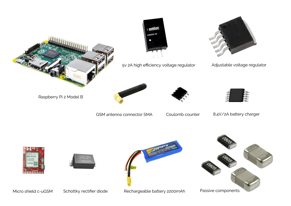 Figure 1. Some of the required components
All these hardware components must be connected according to the system schematics, as described in the Schematic Diagram section. This project also requires a basic set of laboratory instruments, such as:
- Adjustable voltage source
- Breadboard and wires for initial prototype
- Soldering station for soldering components onto the Power Module
- Keyboard and display for Raspberry Pi
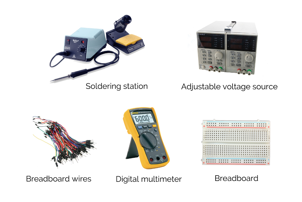 Figure 2. Required Lab Equipment
The Gerber files for the PCB connecting all the components are provided in the GitHub repository. However, for this part of the project it is recommended to contact a factory specialized in PCB production, such as VI&RUS Factory. Placing and soldering on the components can be done either manually at home and soldered using a soldering station, or in a pick-and-place environment and soldered in an oven. One laboratory that provides all these facilities is the CETTI at the Faculty of Electronics, Telecommunication and Technology of Information.
2.2 Schematic Diagram
In the block diagram you can see the components included in the so called ‘Power Module’. This was designed as a separate PCB and links with the ‘RPi 2 Module’ via connectors. The complete schematic diagram of the module is shown in “Figure 4. SMSGate Schematics”.
The schematics for this project were designed to meet all the requirements and provide 24-hour functionality for the system. During development I created 3 versions of the system, v1.0, v1.1, and v1.2, each a slight improvement on the previous version.
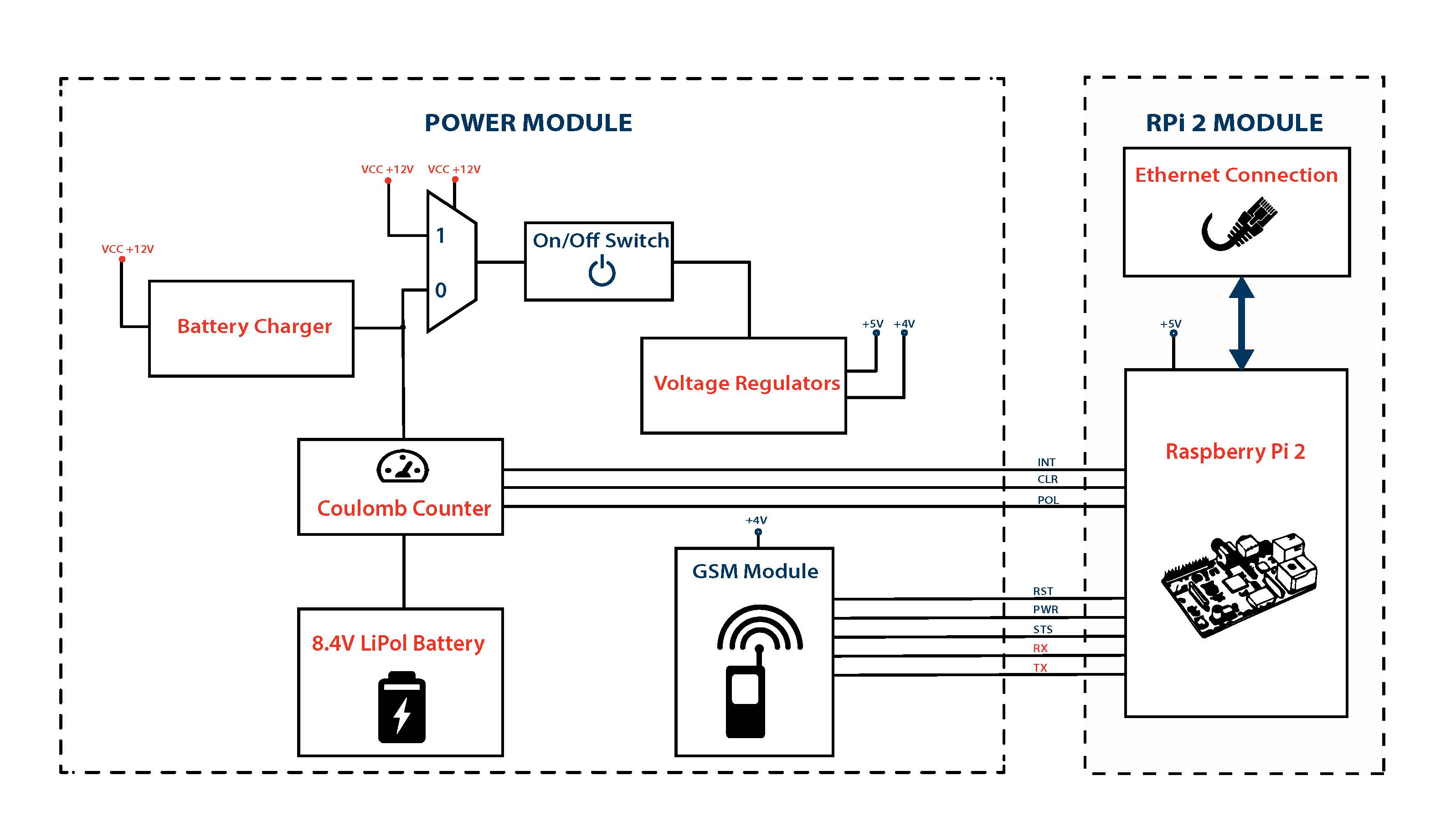 Figure 3. Block Diagram
 Figure 4. SMSGate Schematics
The ‘Power Module’ blocks was designed as a separate PCB and links with the ‘RPi 2 Module’ via connectors.
2.2.1 The RaspberryPi to GSM Module interface
The GSM module was designed by its producer to be a ‘shield’ for Arduino and Raspberry Pi. It has an integrated battery charger for a 3.7V Li-ion Battery that you can choose whether to connect or not.
There are multiple ways of powering it up:
- +4V on Vcc 4V IN pin (between 3.6V and 4.2V is accepted) from a switching-mode power supply (recommended) without a LiPo battery
- +5V on Vin 5V LiPo IN with a 3.7V LiPo battery connected. The +5V is used to charge the battery that powers up the module
- USB connection for power with 3.7 LiPo battery connected
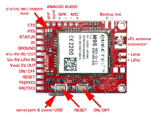 Figure 5. c-uGSM Module Top View
2.2.2 Powering up the system
For v1.2 (final version), I chose the first way of powering up the c-uGSM module (external +4V power source) using a switching voltage regulator with a high efficiency (93%) to save as much battery power as possible. There is no 3.7V LiPo battery connected to a charging circuit and I designed a charging circuit for the 8.4V LiPo battery in the system.
2.2.3 Coulomb counter
In order to keep track of the battery level, I added to the schematic diagram a coulomb counter which sends the RPi an interrupt signal every time a fixed amount of current passes from the battery to the system or vice versa. The current flow direction is indicated via the POL signal. If the POL is logically ‘True’ then the battery is charging, and if it is logically ‘False’ it is discharging (i.e. current flowing from the battery to the SMSGate).
2.2.4 Charging circuit
The charging circuit was implemented using a BQS2057WSN IC, which charges the battery with a constant current of 200mAh. This value was chosen to be so small as to provide a long life for the battery and bearing in mind the use case for this back-up power supply: i.e. only in extreme situations when the power is down.
I chose the transistor which drives the battery current flow carefully after taking into account all possible limitations, such as power dissipation or voltage drops. One issue I was lucky to spot and able to resolve on time was that the thermistor employed as a temperature sensor required a 10uF capacitor to be used in parallel with it in order to prevent the following situation: when the battery is low and the power comes back from the line, the charging process does not start. This is due to a glitch in the current running through the thermistor and its voltage divider (R6 and R11), causing the NTC thermistor to increase its own temperature, which in turn leads to a drop in resistance and, as an automatic consequence, a low voltage. This low voltage from the sensor lies outside the range within which the charging circuit does its job, which explains the initial issue.
2.3 Initial versions
During the first tests I used the second type of power-up method as described in the Schematic Diagram section. I connected the STATUS, ON/OFF and RESET to 3 GPIOs from the Pi and of course the RX to the Pi’s RXD and TX to the Pi’s TXD. In this type of connection, the GSM module should have a 3.7V LiPo battery attached to its own on-board charging circuit. Besides this I also added a 3.5” Adafruit display to eliminate the need for an external display to perform initial tests. I powered up the whole system using a 5V brick power pack, taking the opportunity to build my own Raspberry Pi powered microcomputer while working on the SMSGate project. Figures 6 and 7 show the realization of the initial version 1.0
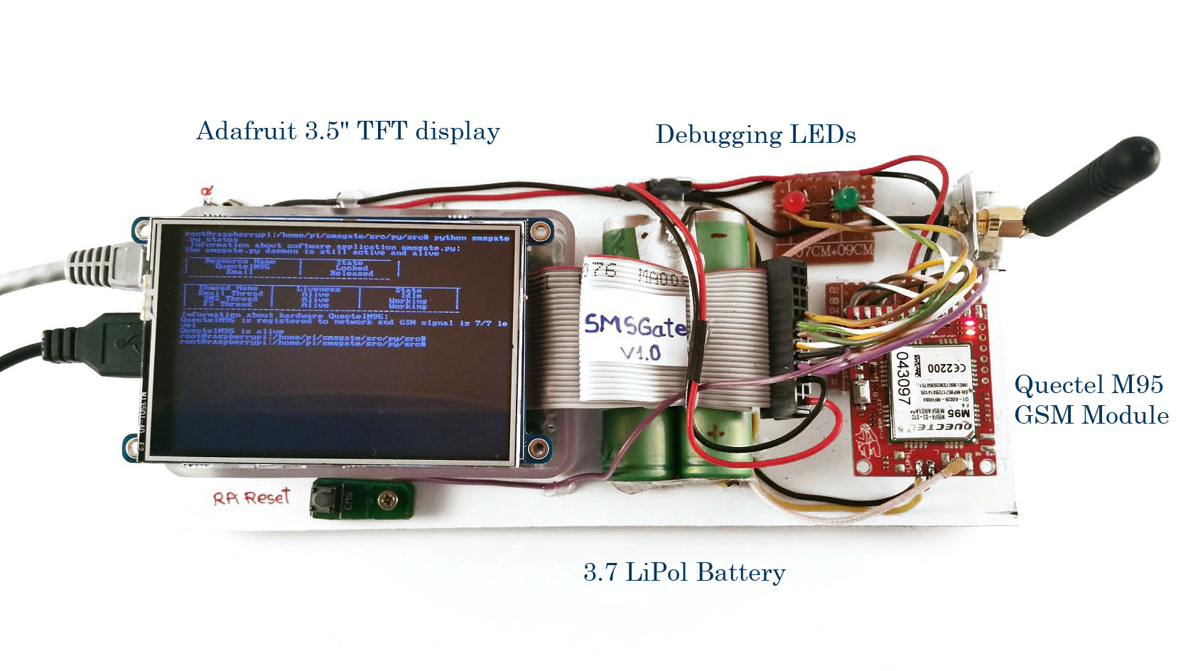 Figure 6. SMSGate Implementation V1.0 – Top View
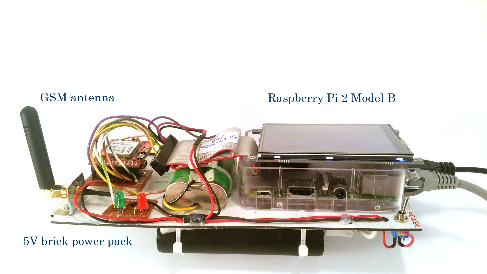 Figure 7. SMSGate Implementation V1.0 – Rear View
This approach was only good enough for the initial tests because of the need for two separate batteries, one for the GSM module and one for the Raspberry Pi.
For the second version (v1.1, Figure 8), I produced the PCB in the laboratory using Press and Peel technology based on the above schematic diagram …. but with a tweak: the logic of switching between Power Line and Battery inputs (when the power line is not available) was implemented using a relay. This solution resulted in a switch time that was way too slow (~2ms), causing the RPi to detect a low voltage. Given the well-known limitations of P-n-P technology, I knew I would be unable to design the correct pads for the coulomb counter, i.e. an integrated circuit with a row pitch of only 20 mil , so I bought a pre-assembled module from SparkFun.
I won’t bore you with details of what goes into the production of a PCB, but will instead delight you with a couple of pictures (Figure 8. and 9.) of this time-consuming but rewarding task.
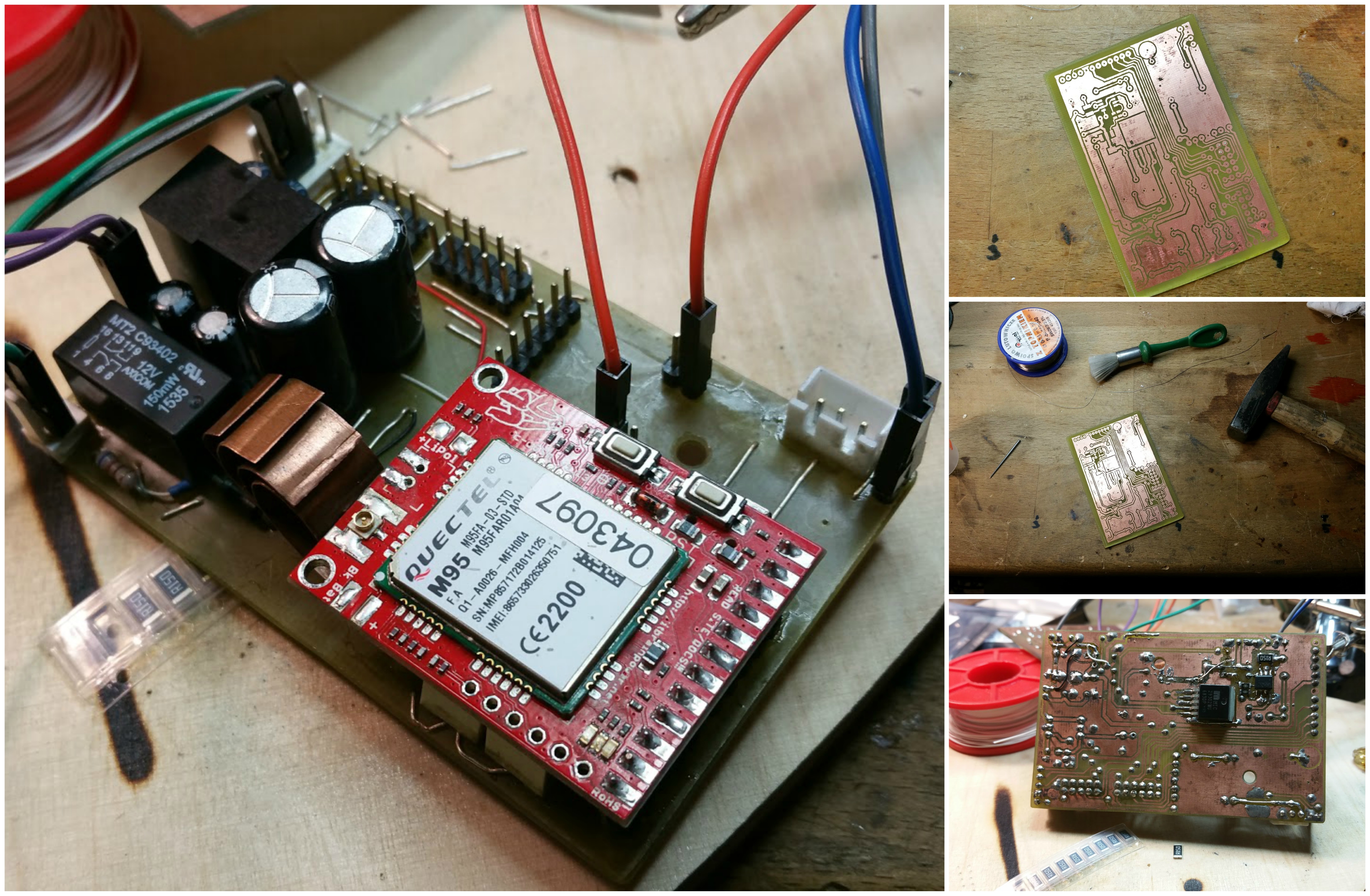 Figure 8. SMSGate Implementation V1.1 – Progress Snapshots
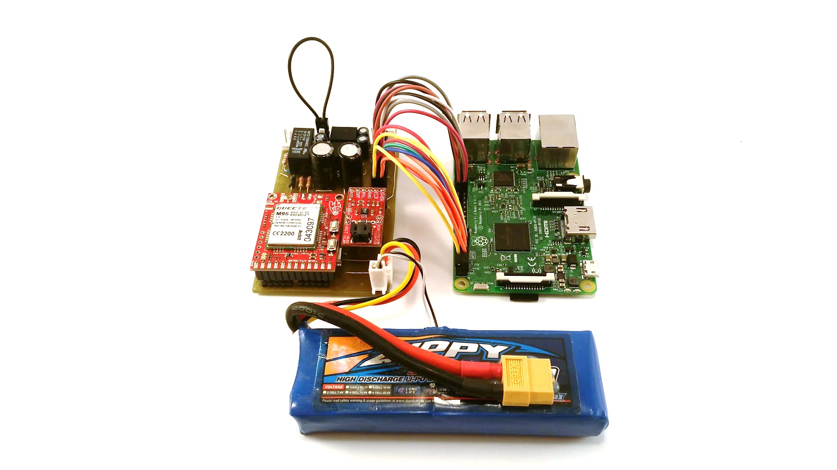 Figure 9. SMSGate Implementation V1.1
2.4 Assembling the hardware
As the relay was not providing a satisfactory switching time, I decided to redesign the power module, replacing the relay with two low-voltage drop Schottky diodes, as shown in Figure 4 in the Schematic Diagram section. In order to overcome the limitations of the Press and Peel technology used in version 1.1, I decided to send the project to a PCB manufacture factory. This gave me the opportunity to integrate the coulomb counter into the design of the PCB, rather than using a breakout from SparkFun.
So for the final version of the PCB I resolved all the issues encountered and redesigned the whole layout before sending it to the factory (VI&RUS Factory). I placed and soldered the SMD components in the CETTI laboratory at the ETTI Centre.
Figures 10 and 11 show the PCB and final, connected, implementation.
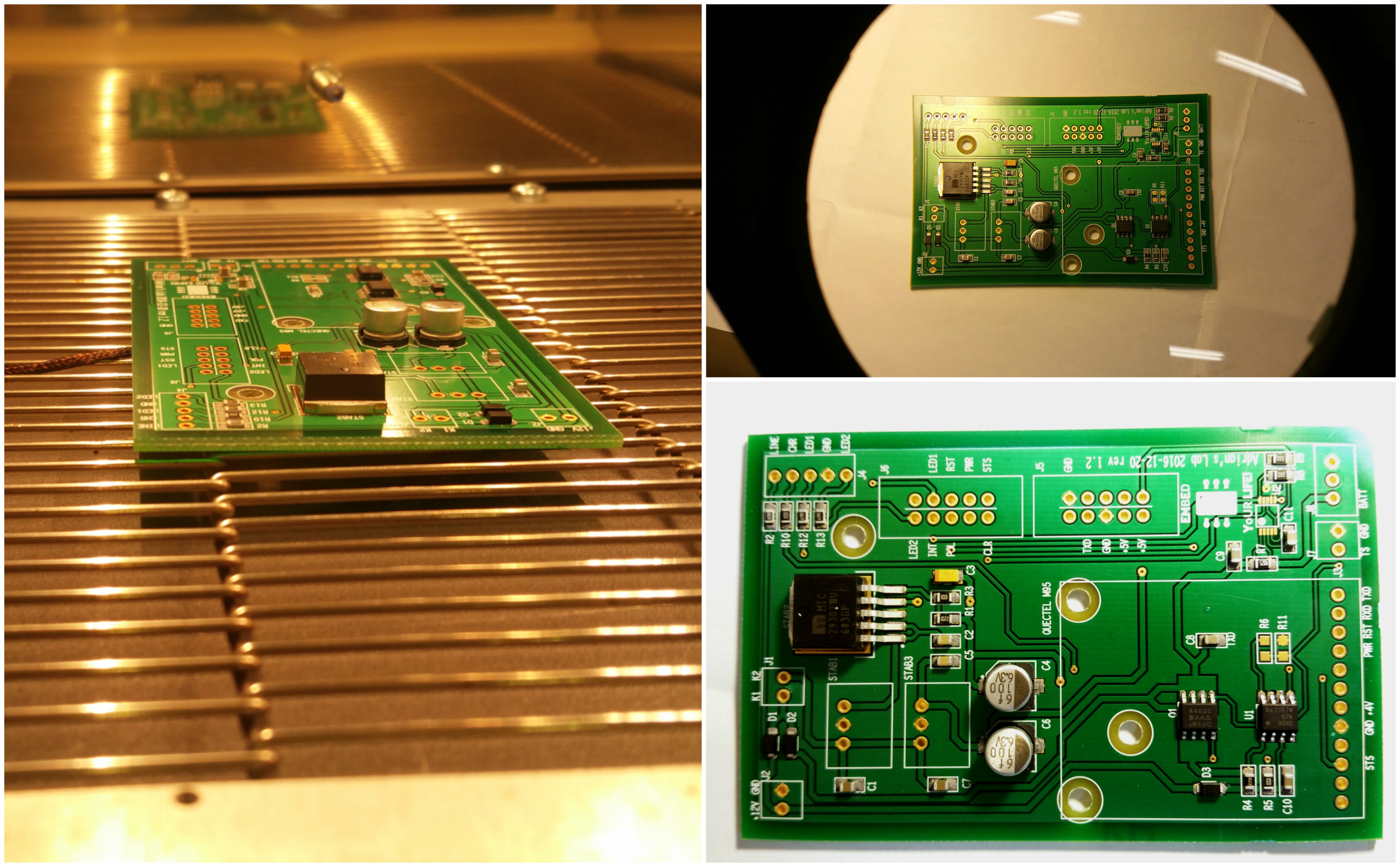 Figure 10. SMSGate Implementation V1.2 – PCB
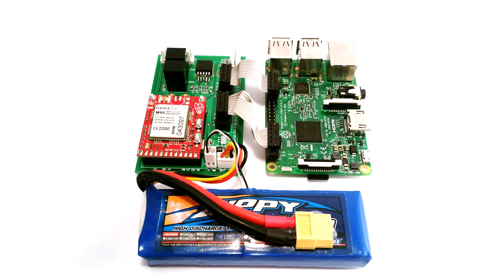 Figure 11. SMSGate Implementation V1.2
3. Software
3.1 Installing the required software on the laptop
For the software development I used a basic laptop with the following installed:
- Ubuntu 16.04.1 LTS on a laptop or desktop work station
- PyCharm EDU or any other Python IDE
- GIT and a GitHub account
To edit and test the Python application I used PyCharm by JetBrains. You can of course use any kind of Python code editor, even the pre-installed gedit on Ubuntu.
By default, all modern versions of Ubuntu come with Python 2.7 pre-installed. You can check this by typing the following into the command line:
python2.7If you receive confirmation then you already have it installed. In the unlikely event that you don’t, then type the following into the command line:
sudo apt-get install python2.7You should install RPi.GPIO on your laptop in order to avoid compile errors. Although this will eliminate compile errors, you won’t be able to fully test the application on the laptop (as you don’t have GPIOs on your laptop).
You may also wish to install Terminator, which is a useful tool for arranging multiple terminals on the screen at the same time (the screen is split into multiple areas, each hosting an independent terminal). You can install this by typing the following into the command line:
sudo apt-get install terminator3.2 Installing and configuring Raspbian
- Download Raspbian. The lite distribution should do as no GUI is needed.
- Insert the SD card and boot the Pi for the first time
- Upgrade and update packages by typing the following into the command line:
sudo apt-get update
sudo apt-get upgrade- Install the Minicom serial communication application, Vim text editor and some more Python libraries:
sudo apt-get install minicom
sudo apt-get install vim
sudo apt-get install python-serial
sudo apt-get install python-dev python-rpi.gpio- Enable UART communication
sudo vim /boot/config.txtChange enable_UART=0 to enable_UART=1.
- If you use RaspberryPi 3 you should disable the Bluetooth peripheral:
sudo vim /boot/config.txtUpdate dtoverlay field to be: dtoverlay=pi3-disable-bt and then run:
sudo systemctl disable hciuart
3.3 Cloning the GitHub repository
First, if not installed already, you need to install Git on Raspbian:
sudo apt-get install gitThen clone the GitHub repository on your Raspbian system:
git clone https://github.com/razdrian/smsgate.gitNow create a new folder called smsgate in /var/ and copy into it the entire contents of the /var_smsgate folder from the repository you just cloned. Make sure these folders are created: /var/smsgate/input, /var/smsgate/output/savedsts, /var/smsgate/output/savedlogs and /var/smsgate/output/savedtxt, otherwise create them.
Move the smsgate file from the repository to /etc/init.d. This file contains the Raspbian service functionality. Create a symbolic link called K02smsgate in directories /etc/rc0.d, /etc/rc1.d and /etc/rc6.d:
cd /etc/rc0.d
sudo ln -s /etc/init.d/smsgate K02smsgate
cd /etc/rc1.d
sudo ln -s /etc/init.d/smsgate K02smsgate
cd /etc/rc6.d
sudo ln -s /etc/init.d/smsgate K02smsgate
Create a symbolic link called S01smsgate in directories /etc/rc2.d, /etc/rc3.d, /etc/rc4.d and /etc/rc5.d by typing the following command each time in the corresponding directory:
cd /etc/rc2.d
sudo ln -s /etc/init.d/smsgate S01smsgate
cd /etc/rc3.d
sudo ln -s /etc/init.d/smsgate S01smsgate
cd /etc/rc4.d
sudo ln -s /etc/init.d/smsgate S01smsgate
Now the SMSGate application is ready to be run as a Raspbian service, which means it can receive commands such as start, stop, restart or status. A detailed status of the system will be outputted to /var/smsgate/livestatus.txt file every time you type:
sudo service smsgate status3.4 Setting up the connection between laptop and Raspberry Pi
To transfer files to the Raspberry Pi from my work station running Ubuntu and Pycharm IDE, I used the GitHub with commits and pushes from the laptop and pulls from the RPi.To be able to access the Raspberry Pi system easier, I naturally used an SSH connection and SSH-key authentication in order to skip the password input requirement every time I logged on.
Below is a photo of the laboratory set-up in which I developed the software application. On my laptop I used Terminator as I mentioned before, two terminals logged in via SSH to the Raspberry Pi and one terminal on my local machine. Of course, both were connected to the same local network.
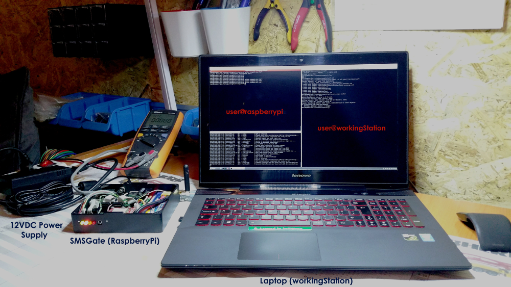 Figure 12. SMSGate…alive
3.5 Setting up the application
Configuration of the system is achieved in two ways:
- Setting the globalPara.py file in /smsgate/src/py/lib. More about this in the User’s Guide available in the Resources section.
- Setting up the phonebook.json from the /var/smsgate/ directory. Here you can add user information and add users to an existing group or a newly created one.
4 System Housing
To house the entire system I designed a case made out of Perspex. I drew up the design on paper and indicated how the components should fit into it, and a friend at Modulab then helped me translate the paper design into a Fusion 360 project. The final 3D version of the SMSGate case is available for public download here and looks like this:
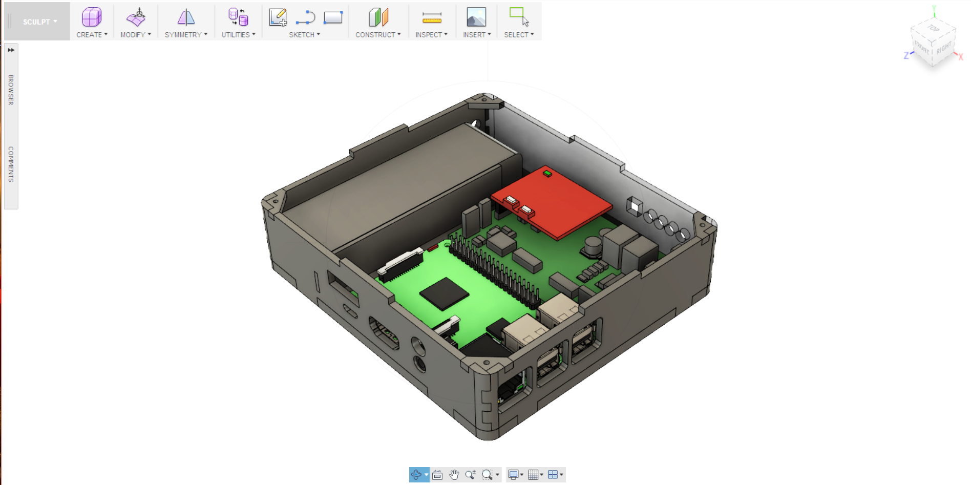 Figure 13. Fusion 360 Box Project
Each piece was exported as a DXF file and cut out using a laser cutter. The box was then glued together using an adhesive and the joints were covered with body filler. Finally, the entire box was painted using a matt black spray paint to give it a nice and even look. The pictures below show different stages of box development.
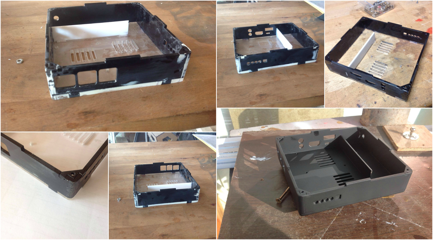 Figure 14. The Box – Work in progress
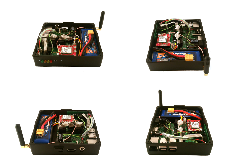 Figure 15. The final product is almost ready
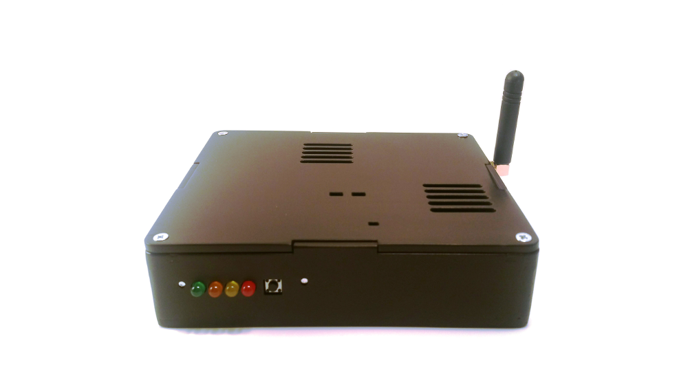 Figure 16. The final product is ready to be shipped
5. Application demo
The application supports few work flows: SMS-to-Email, Email-to-SMS, SMS-to-Command, FileSystem-to-SMS etc. Their setup, SMS/Email/File formats are described in the User Guide.
Basically all you have to do is to configure the system, power it up and wait for it to connect to the GSM network.
The Email-to-SMS work flow allows users to forward emails to SMS. Picture 17 shows an example of Sms to Email flow.
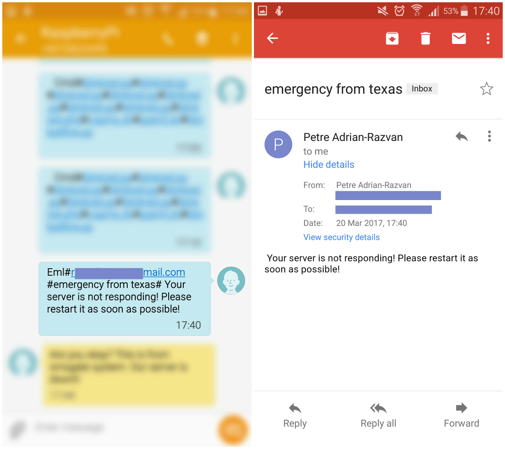 Figure 17.The SMS-to-Email Example
The Email-to-SMS work flow allows users to forward emails to SMS. Picture 18 shows an example of Email-to-Sms flow.
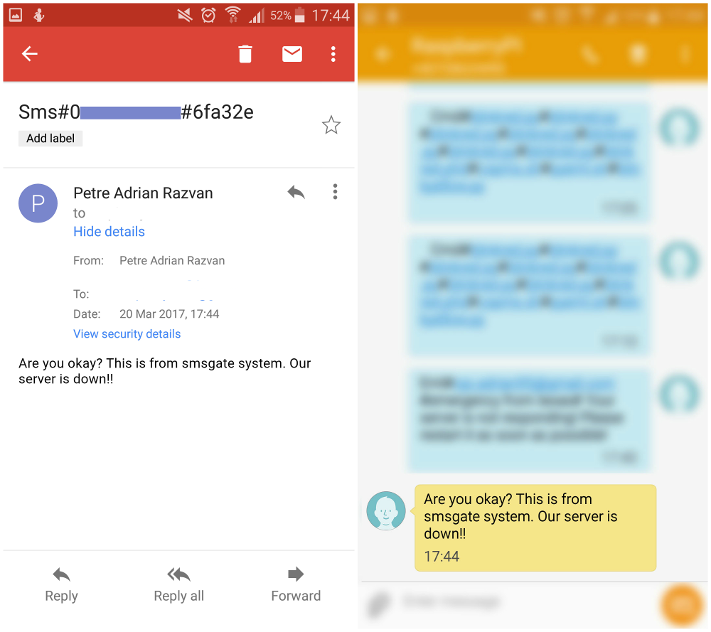 Figure 18.The Email-to-SMS Example
The SMS-to-Command work flow allows users to execute scripts under /var/smsgate/commands folder through the SMS channel. In order to activate this flow you need to make sure 1) the script you want to execute exists under /var/smsgate/commands, 2) it is executable and 3) the sms obeys the format specified in the User Guide.
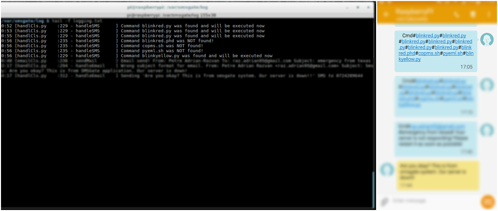 Figure 19. The SMS-to-Command Example
6. Future enhancements
The first enhancement has to do with an inherent drawback of the entire system: the email POP and IMAP connections are made exclusively via the Ethernet cable. If this network fails, only the SMS flow remains active. Therefore, it would be a major improvement to have internet access via the GSM module, i.e. completely independent of the local network internet connection. Keep a watch on the GitHub repository if you need this feature.
A second improvement would be to integrate into the application a Wake Up on USB feature for the Raspberry Pi in the unlikely event of an automatic shutdown. This would only take place after a long period of power loss, during which the Raspberry Pi would run on battery power, which would eventually run out. The wake up signal would be sent from an external device such as an UPS power supply when the power comes back on.
A third enhancement that comes to mind would be to move the system core from a Raspberry Pi 2 to a Raspberry Pi Zero. This micro-computer only costs around $5 and is able to run the basic Raspbian OS and the SMSGate application. It features a 1GHz single-core CPU and 512MB of SDRAM. It would need an Ethernet module, but this only costs a couple of dollars more. The Pi Zero is well known for its very low power consumption, which could increase the battery uptime of the system.
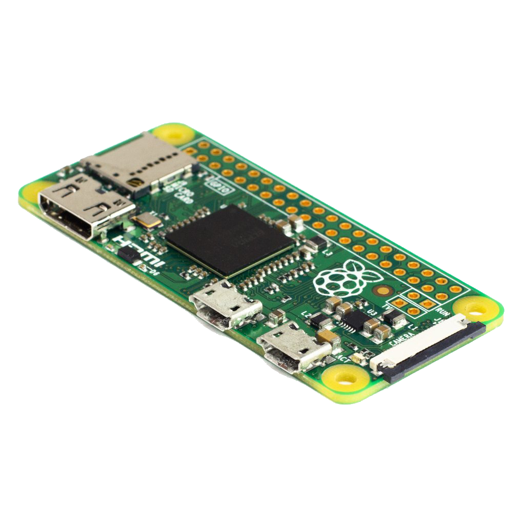 Figure 20. RaspberryPi Zero
Last but not least, the charging circuit for the LiPo battery could be improved. A typical lithium polymer battery cell has a nominal voltage of 3.7V and higher voltages are obtained using battery packs that contain cells connected in series. When charging an 8.4V battery pack, such as the one used in this system, balancing voltage over the two cells becomes an issue. This means that the voltage drop over one element could be a couple of millivolts higher than over another, which in time could led to the malfunction of one element. To prevent this, a special IC that would continuously measure the voltage over each element and adjust it as required should be added to the schematic diagram.
7. Acknowledgements
First of all, I would like to thank Dragoș Iosub from ITBrainPower for the library sketch provided with the GSM Module. The communication with the GSM module in SMSGate application is based on this API, which was a very good starting point.
I would also like to mention Matei Popescu, Product Designer at Modulab, art, science and technology center, for his help with the design and manufacture of the SMSGate case described in the System Housing section.
Both the PCB design and the sending of Gerber files to the factory were supervised by Dr. Ing. Mihaela Pantazică from the CETTI center who assisted me during the design process and helped me with the final touches of the circuit board.
Electrical design flaws were resolved with the help of Dr. Ing. Florin Drăghici, Basic Electronic Circuits Professor in the Electronic Devices, Circuits and Architectures department of Faculty of Electronics, Telecommunication and Technology of Information.
Last but not least, this project was developed with the support of the AMIQ Education Program, with AMIQ providing the necessary components and mentoring (technical and “business”-related support).
8. Licenses
The SMSGate application is Licensed under the Apache License, Version 2.0 (the “License”). You may not use this file except in compliance with the License. You may obtain a copy of the License here.
Fusion 360 gives a 3-year education license for students and educators. The free license is provided after email verification.
OrCAD Cadence has a lite version that has a maximum limit of 50 components as well as a couple of other restrictions, but is absolutely free for study purposes.
PyCharm Edu is free & open source. It is licensed under the Apache License, Version 2.0. It is specifically targeted at students and designed to help students learn to program in Python.
9. Resources
[1] Terminator – useful tool for arranging terminals
[2] Pycharm Edu – free, easy and professional Python programming tool
[3] OrCAD Cadence Lite – OrCAD Capture CIS for schematic diagram design and PCB editor for Gerber files
[4] GerbTool by WISE Software, free trial download for inspecting Gerber files.
[5] Fusion 360 AUTODESK – 3D CAD and CAE tool
[6] About Epydoc documentation
[7] Free UART from RaspberryPi
[8] Logging in Python
[9] About IMAP and SMTP
[10] Unitest in Python
[11] Unix daemon in Python
[12] Python script running as Daemon in Linux
[13] Poplib in Python
[14] Parsing a raw email
[15] Imaplib example using Gmail
[16] Threading in Python
[17] Getting a Python script to run in the background
[18] Disable Bluetooth to make serial work on RPi3
[19] Best Guide to Li-ion and LiPo battery charger
[20] How to make your own PCBs at home
[21] SMSGate User Guide
2 Responses
Congratulations Răzvan. Final product looks real neat and professional. This is a very good initiative from AMIQ.
Adrian, very well done!
I just quickly parsed your project. Definitely it is ABOVE regularly integration projects approached by a young people… it’s looking more as a integration project approached by one professional.
Again, WELL DONE!
Dragos Iosub [itbrainpower.net]