For precise and effective data transfer, serial communication depends on clearly defined protocols at the Physical and Data Link layers. The conversion of binary data into reliable signal patterns for physical transmission is the main emphasis of this short read exploration of line encoding and data transformation techniques.
1. Physical Layer: Line Encodings in High-Speed SerDes
In serial data transmission, line encoding is essential because it converts binary data into signal patterns that can be reliably transmitted over physical channels. Non-Return-to-Zero and Differential Non-Return-to-Zero are the two main encoding strategies employed in this SerDes design.
Particularly at large data rates, these techniques guarantee signal integrity, lower transmission errors, and make clock recovery easier.
NRZ (Non-Return-to-Zero)
NRZ is a simple line encoding method where:
- Logic “1” = High voltage level (~5V)
- Logic “0” = Low voltage level (0V)

In the image above, the bit sequence “010110” is encoded using NRZ. Data is driven and sampled on the rising edge of the clock, and the signal holds its value for the entire clock cycle.
DNRZ (Differential Non-Return-to-Zero)
DNRZ is a differential line encoding method where:
- Logic “1” = Voltage transition (swap polarity between differential pairs as N->P, P->N)
- Logic “0” = No transition (maintain previous state)

In the image above, the bit sequence “010110” is encoded using DNRZ. Data is driven on the negative edge of the clock and monitored on the positive edge. At T1, there is no transition since a 0 does not change the signal state. At T2, a 1 causes the signal to transition to a low level.
2. Driver and Monitor Logic
The driver is responsible for applying the encoded data onto the interface in accordance with the selected encoding scheme and the corresponding clock edge.
 virtual task drive_based_on_line_encoding_method(
        input amiq_line_encoding_method_t line_encoding_method,
        input bit value
        );

        case (line_encoding_method)
            CLOCK_NRZ : begin
                @ (posedge vif.tx_internal_clk);
                vif.s_data_tx <= value;
            end

            CLOCK_DIFFERENTIAL_NRZ : begin
                @ (negedge vif.tx_internal_clk);
                if (value == 1)
                    vif.s_data_tx <= !vif.s_data_tx;
            end
        endcase
    endtask
The monitor samples the signal on the positive edge of the clock and decodes it back into logic bits, depending on the encoding scheme:
virtual function void sample_bit(bit current_bit_on_vif, ref bit current_bit, ref bit prev_nrzi_value);
        bit current_signal_value;

        case (cfg.line_encoding_type)
            CLOCK_DIFFERENTIAL_NRZ: begin
                current_signal_value = current_bit_on_vif;

		   current_bit = (current_signal_value == prev_nrzi_value)
				    ? 0 : 1;

                prev_nrzi_value = current_signal_value;
            end

            CLOCK_NRZ: begin
                current_bit = current_bit_on_vif;
            end
        endcase

    endfunction
3. Data Link Layer: 8b/10b, 64b/66b
Although signal synchronization and basic data representation are guaranteed by line encoding schemes like NRZ and DNRZ, they sometimes have trouble sustaining a sufficient number of transitions and achieving DC balance over longer transmissions. Block encoding schemes are used to get around these issues and enhance signal reliability at higher data rates. To guarantee specific desired characteristics in the physical signal, these techniques transfer a collection of data bits into a wider set of transmission bits. Two popular systems include 64b/66b encoding, which is intended for even faster networks like 10 Gigabit Ethernet, and 8b/10b encoding, which is widespread in standards like Gigabit Ethernet and Fibre Channel.
8b10b Encoding
The 8b/10b encoding works by mapping each 8-bit data byte into a 10-bit transmission character also known as a codegroup/symbol. This transformation is not arbitrary. It’s designed to maintain DC balance(an equal number of 1s and 0s on the bus) and ensure a sufficient number of bit transitions for clock recovery.
Each 8-bit input is divided into two parts:
- The first 5 bits (called the 5b group or x) are encoded into a 6-bit code (6b).
- The remaining 3 bits (the 3b group or y) are encoded into a 4-bit code (4b).
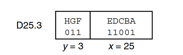
Together, these produce a 10-bit output symbol.

There are two possible 10-bit encodings for each 8-bit data byte: RD- and RD+. By alternating between these, the encoder keeps the number of 1s and 0s almost equal over time, preserving DC balance. This guarantees dependable clock recovery and stops signal drift in AC-coupled links. The encoder tracks the current disparity state (RD- or RD+). For each byte, it selects the encoding that flips the disparity: if the bus has too many 1s (RD+), it picks an RD- symbol with fewer 1s, and vice versa.
64b66b Encoding
Each 64-bit data block is converted into a 66-bit transmission block using 64b/66b encoding. High-speed communication systems like 10 Gigabit Ethernet, where preserving signal integrity and reducing overhead are crucial, are the main applications for this technique.
64b/66b adds only about 3% overhead, which is far more efficient for huge volumes of data than 8b/10b, which adds 25% overhead.
A 2-bit field, known as the sync header, precedes each 64-bit data block, forming a 66-bit block.
- The 2-bit prefix indicates the type of block:
- 01 = Data block
- 10 = Control block
- The remaining 64 bits carry either data or control information.

Unlike 8b/10b encoding which relies on running disparity for DC balance, 64b/66b uses a scrambling technique that maintains signal integrity more efficiently(The scrambler’s seed is set at the start of the simulation). This method eliminates the need for the combined 5b/6b + 8b/10b algorithm when mapping bytes to symbols, offering better efficiency.
The scrambling is based on a specific polynomial (typically G(x) = 1 + x39 + x58). This allows the receiver to descramble the frame and extract both control information and user data reliably.
That’s all! Read, Share and Subscribe to keep the community alive!